[Plugin][$] Curviloft 2.0a - 31 Mar 24 (Loft & Skinning)


-
@escapeartist said:
Fredo,
I don't know if this has already been discussed, but there seems to be an issue with "loft junctions following two paths". I create a shape using bezier curves and then convert them to polyline dividers. The script does a really nice job making the overall shape, the problem is along the seam where the profiles meet. It may be due to a mismatch in the number of segments in the edges from one side to the other, but Curviloft creates extra faces that are "folded" into the geometry and are essentially invisible until one goes in and starts moving verts around. The cause a visible seam to show up when shaded smooth. The only solution I know of is to go through and find each face and reconnect/rebuild each edge and face to remove them. Any suggestions on how to better avoid this extra work? Is it as bug or simply an issue with my modeling?
Would have the model so that I can have a look.
This seems strange, but Curviloft algorithms have some shortcuts for performance reasons which may explain a few issues like this one.Thanks
Fredo
-
@EscapeArtist:
That second image looks like rather than "extra" reversed faces, you have pulled the mesh somewhat inside out because additional edges need to be placed. The additional edges would be placed only in order to get additional vertices. Adding edges will avoid seam ripping which is what appears to be happening here.
I am just saying this from my experience with detail "knitting" on meshes.
Of course, I am probably wrong.. again
-
@mitcorb said:
@EscapeArtist:
That second image looks like rather than "extra" reversed faces, you have pulled the mesh somewhat inside out because additional edges need to be placed. The additional edges would be placed only in order to get additional vertices. Adding edges will avoid seam ripping which is what appears to be happening here.
I am just saying this from my experience with detail "knitting" on meshes.
Of course, I am probably wrong.. againThe model is as-is Curviloft output, the pulling was done in order to reveal the extra edges and faces. The face isn't visible until the vert is pulled out of alignment because the edges are so close together as to appear to be a single edge. I did re-stitch the seam and it looks OK but for the slight ripple created by my inability to precisely match the desired curvature by hand.
Fredo, the model and curves are attached.
-
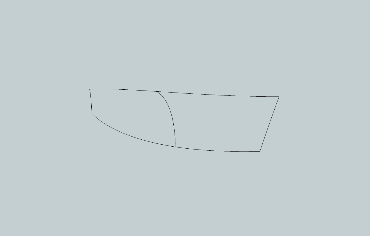
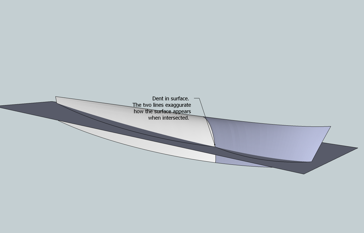
Dear Fredo6. I use curviloft extensively (for boat design purposes) and am very grateful for it. But there is an issue that I would like to address: When making hull sides for boats, I create two compound curves. You can see it in the attached images. The upper line is the deck- line, the lower one is the so- called chine. The left side is where the transom is, the right side is the stem. In the middle, there is a line that defines a flare in the bow- sections of the boat. Ideally, Curviloft would create a smooth panel from these lines, but no matter how I do it (skinning, path or lofting), Curviloft seems to do it in a different way than expected, the result being a dented surface.
For example, if I selected the middle line first or last, I would expect a different outcome then when it is selected subsequently from left to right or vice versa. Curviloft seems to think of it like two surfaces instead of one, just like the colors indicate. Occasionally the color is the same for the whole panel, but it still appears to be dented.
I may be asking too much of Curviloft, but if there is a way that I have not detected yet, then I would appreciate that.
PS I have installed latest (January 2011) versions of Curviloft and Libfredo
Best regards Teo
-
Hi All
Been using this for only a few days and its great
Now i'm trying some more tricky shapes with odd results
On a simple shape i click on each line and it comes up 1,2,3,4 and skins
Then sometimes I click and it comes up 1 with an orange line, next line 1 again and orange and so on. When I click the green tick all the lines turn purple
Does this mean its too much for CL?
Thanks -
@deanlegg said:
Hi All
Been using this for only a few days and its great
Now i'm trying some more tricky shapes with odd results
On a simple shape i click on each line and it comes up 1,2,3,4 and skins
Then sometimes I click and it comes up 1 with an orange line, next line 1 again and orange and so on. When I click the green tick all the lines turn purple
Does this mean its too much for CL?
ThanksWhen contours are contiguous, you need to click in the empty space to separate them. Otherwise all portions are taken as part of the same contour.
When contour are not contiguous, then the 'separator' is not necessary.Fredo
-
I have to say this is one of the Coolest PlugIns I have seen for SketchUp!
BRAVO Fredo6 !
I am using CurviLoft 1.1, Loft along Path, and I am creating some geometry that is amazing. It took several tries to get the exact geometry I envisioned. I'll keep working with the Tool.
One Problem I am having is when I use the INTERSECT with Model tool to intersect the Fin Top I created with Curviloft with the Dome Shape I created using sketchup followme tool, the Shape I created with Curviloft gets weird (after intersect with selected), and adds extra Lines and distorted geometry. I need to trim the Shape, and then Hide lines, but the geometry gets funky using the intersect process in SketchUp. How do I only select the countor Lines on the END of organic geometry w/o selecting the entire mesh face? I would like to HIDE the Lines/etc. Do I need to use "Tools on Surface" in order to work with created shapes in Curviloft? I'll be painting it soon as well.
Basically, I Need to Trim a Shape!I am really digging this Organic Modeling Tool for SketchUp Fredo6
Thanks - Andrew Telker
http://twitter.com/AndrewTelker


-
I really need this plug in!!!!
thanks!!!!! -
That's really help me alot.
but how come i cannot install it in my skp?! -
@on2wong said:
That's really help me alot.
but how come i cannot install it in my skp?!Read [and understand] the instructions on the download page about what needs downloading [including the Lib stuff that you have to get separately], and then ensure that you put everything in the correct place[s], then activate the tool's Extension and Toolbar etc... Using it's the easy part

-
escape artist
Any chance to get the above example loaded to the 3 d ware house so it can be open in SU7.Other wise I have to go dfx and then Su7. Getting these results and would like to see if the conversion is causing problems

-
mac1
I've just made EscapeArtist's example.skp into v7 - try downloading it again from the same post... http://forums.sketchucation.com/viewtopic.php?p=309006#p309006
-
@tig said:
mac1
I've just made EscapeArtist's example.skp into v7 - try downloading it again from the same post... http://forums.sketchucation.com/viewtopic.php?p=309006#p309006
Thanks.
-
TIg
Thanks.
As a point of clarification. I am not implying there is any thing wrong with the plugin. I found cases where I have made simple models that show this character and think it is caused by my sloppy approach of applying some of the constraints one must follow when modeling especially when using the follow me tool. I have a feeling if the suggestions made by Fredo are followed this my not show up or its the hand springs I am going through to get the model.
Thanks again -
Escape Artist
Some observations ref your model for what they are worth:
1)I was expecting to see the bulk head curve length for what I thought was the keel line to each side to be equal but in most cases there is almost a 2 to 1 difference. Not boat designer, is this normal??
2) At bulk head number 2, counting from stern as #1, this is an obvious kink in the "keel" curve fit just before #2. This IMHO maybe causing some problems. Better tangent here my help??Still seeing the self intersecting faces in the SU model but only 1( 4 to 5 range before) after the deletion of duplicte vertices which are now 1714 vs 6983 so my hand springs to get from SU8 to SU7 causing some problems.
You may want to run ThomThom,s clean up tool to see if it helps any. That can be done with in SU. It will not give same stats as quoted above. I used TIG's extrude by rails and it gives the same ripple in the surface at the area mentioned above as Fredo's tool does and reason for looking there.
I will be doing more checks and will let you know if I find anything more of interest
Good Luck
UpDate Date 3 Apr1) Yes I noted shortly after post the model is only portion of Hull;
2) Self intersecting faces traced to dae and /or kmz conversion I do to get into mesh tool. Kmz gives same result but if dae does not have the option of triangulate set then it does also. With it set see only very few and these can be deleted and corrected in SU
3) Attempting to better fit the chine using a cubic spline interpolation did not give any significant changes in surface result -
While playing with Curviloft (CL), drawing a practice non-scaled air duct for one of my airplane models, I noticed something about how CL handles some defining elements.
My model starts with a tilted ellipse, travels straight back then up over a spar forming a "D" shape (flat side of "D" down), then transitions down to a circle at the engine intake.
I can't show a picture as my old GPU produces solid black export JPG's with SU-V8 due to SU-V8 needing OpenGL 1.5 and my GPU can only handle OpenGL 1.3, so it has to be words only.
The shape was formed with an ellipse, then the "D" shape and a circle, with a long curve depicting how the shape will transform, essentially along the centerlines of the 3 defining shapes. My first tries came out pretty good, taking about 5 seconds to plot the surface. Compare that with about a week's work trying to get that shape by manually tweaking a mesh, and never getting it right.

Anyway, the transition from ellipse to "D" was too flat. I played with the transition curve a bit but was not satisfied. So, I needed to add an intermediate shape on the transition to more circularize the duct. That would be a circle with the bottom slightly flattened, somewhat egg shaped.
As usual, I created the shape on its 1/2 side, then copied it, moved left, flipped and rejoined the 1/2 copy to its original to form the symmetrical duct. Keep in mind, neither 1/2 shapes were true curves, but were just joined line segments. This became important!

I put CL to work and 5 seconds later got a twisted mess between the ellipse to the new shape to the "D" shape.
 The back duct formed properly.
Nothing I could do prevented that. If I took the intermediate (egg) shape out of the CL definition, the duct formed properly. Put it in and it twisted.

Upon close inspection I noticed that most of the twist started from the right side of the ellipse, went to the left side of the "egg" then back to the right side of the "D". But some parts of that duct formed correctly.
So, after some experimentation, I used the WELD.rb on the copied 1/2 side (without facing) and LO the duct formed correctly.

Some more experimenting confirmed this. CL will form a surface on drawn curves even if they are not "proper curves". But if you copy and flip a non-proper curve (set of line segments) CL will twist the shape as if the copied curve retained parts its pre-flip orientation.
So, if you are getting twists in your surfaces, and any parts of your defining shapes are copied and flipped, make sure you WELD the copied shapes to form a full proper curve.
-
@jgb said:
I can't show a picture as my old GPU produces solid black export JPG's with SU-V8 due to SU-V8 needing OpenGL 1.5 and my GPU can only handle OpenGL 1.3, so it has to be words only.
"Print Scrn" ?
-
@thomthom said:
@jgb said:
I can't show a picture as my old GPU produces solid black export JPG's with SU-V8 due to SU-V8 needing OpenGL 1.5 and my GPU can only handle OpenGL 1.3, so it has to be words only.
"Print Scrn" ?
Good Idea, good thing I thought of it.

I'll try tomorrow am early. I have a bit of time, and I will attempt to recreate the problem/solution and Print Scrn it.
-
@jgb said:
@thomthom said:
@jgb said:
I can't show a picture as my old GPU produces solid black export JPG's with SU-V8 due to SU-V8 needing OpenGL 1.5 and my GPU can only handle OpenGL 1.3, so it has to be words only.
"Print Scrn" ?
Good Idea, good thing I thought of it.
I'll try tomorrow am early. I have a bit of time, and I will attempt to recreate the problem/solution and Print Scrn it.
It is always better to post your model vs jpg, lots of info lost in jpg. You will get better results with model so post in 3d ware house
-
@jgb: as suggested, it would be a good idea to post the skp model so that I can have a look. In principle, Curviloft is not sensitive to Sketchup curves as it works on edges. The only benefit of curves is for the selection process.
Also, when you have twisting, you may try to untwist, by clicking on the section. You get a popupu window and then you can change the value of the twist angles.
Finally, which tool do you use: loft by Spline or Loft Along?
Fredo
Hello! It looks like you're interested in this conversation, but you don't have an account yet.
Getting fed up of having to scroll through the same posts each visit? When you register for an account, you'll always come back to exactly where you were before, and choose to be notified of new replies (either via email, or push notification). You'll also be able to save bookmarks and upvote posts to show your appreciation to other community members.
With your input, this post could be even better 💗
Register Login


Advertisement