[Plugin][$] Curviloft 2.0a - 31 Mar 24 (Loft & Skinning)


-
First of all i would like to say Hi to all of you.
Then i must say to you Fredo. THANKS for this great plugin. You are the man. Keep up the good work...
(PS. will send you some money when i can afford it)Now i must go and play with this greate new cool stuff..

-
Thank you very much Fredo
-
Thanks Fredo, I'll give you feedback for sure !!
Regards
-
Fredo, a most gracious and appreciative "thank you".
-
this is amazing, thank you very much!
when i saw the preview i wondered if this would be able to handle this dilemma.
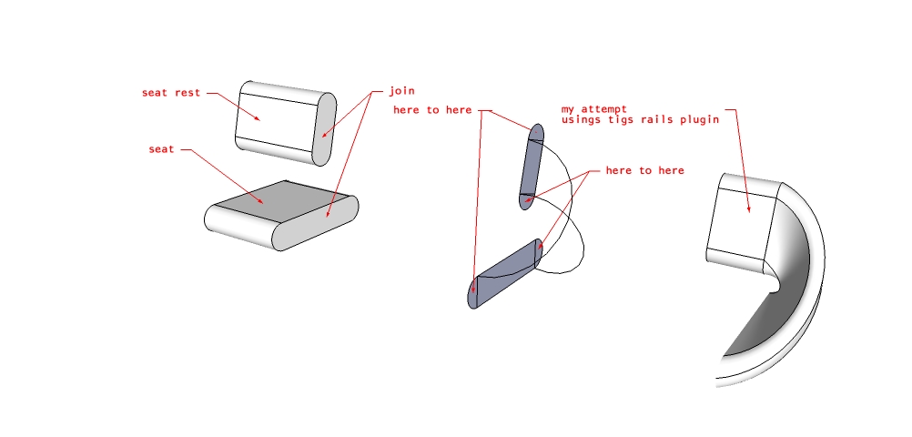
A seat i recently designed needed an end that curved round and formed the back rest. I've just played for 20mins on the beta and i'm struggling. can curviloft help?
cheers
chris
-
Thank you Fredo!!!

The loft tool works very well. All seems very user friendly... and that is very difficult in tools like this ones. The use of your hoverselect tool in the manual selection makes it very simple too.
In the release note you say that there are some limitations and unfinished work.
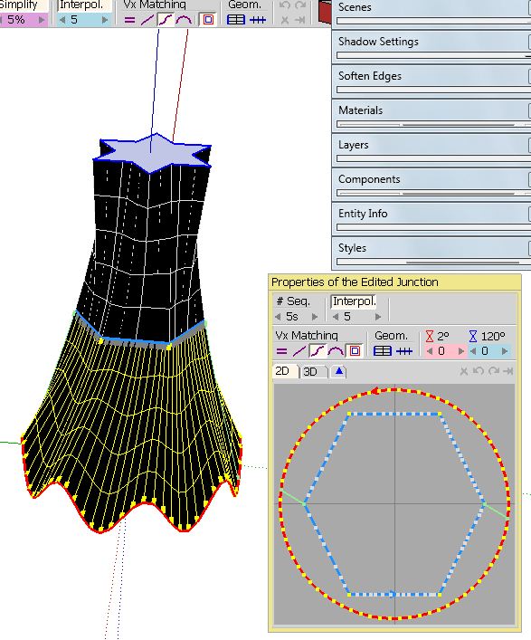
Modify vertex matching by selecting a vertex and dragging it to a new position inside the floating palette is a limitation or a unfinished feature?. That would be awesome.And is possible to allow SketchUp remember the last position of the floating palette? In the default position I have to move it always because there I have all the SU tools there.
Daniel SPS. Can´t wait for the other tools
 Hope that you can realease more beta versions before the "official release".
 -
@cmeed said:
A seat i recently designed needed an end that curved round and formed the back rest. I've just played for 20mins on the beta and i'm struggling. can curviloft help?
cheers
chrisI think you need to draw first the rails that give the shape of the junction, making sure that each surface would be closed by 4 or 3 curves. Then you can apply the Skinning function.
Fredo
-
@daniel s said:
In the release note you say that there are some limitations and unfinished work.
Modify vertex matching by selecting a vertex and dragging it to a new position inside the floating palette is a limitation or a unfinished feature?. That would be awesome.This is rather an unfinished feature. Actually, this is why you have a preview zone in the floating palette, because editing on the model, with faces hiding vertices may be less convenient.
@daniel s said:
And is possible to allow SketchUp remember the last position of the floating palette? In the default position I have to move it always because there I have all the SU tools there.
Daniel SAlso an unfinished feature
@daniel s said:
PS. Can´t wait for the other tools
Hope that you can realease more beta versions before the "official release".The other tools work but may have more issues and unfinished features.
Fredo
-
Hai Fredo, thanks for this pre release ver, im really excited with this capability, thanks againn
regards,
-
I think you need to draw first the rails that give the shape of the junction, making sure that each surface would be closed by 4 or 3 curves. Then you can apply the Skinning function.
Fredo[/quote]
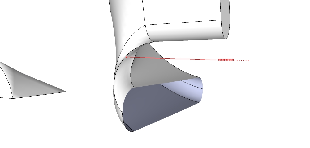
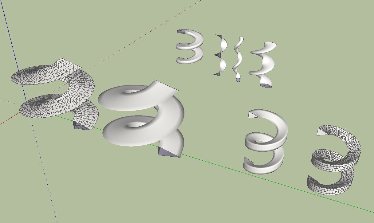
Thanks but i couldn't get the rails working with this. I don't understand it completely yet. i need to wait till the documentation comes out as i seem to find myself with alot of colourful lines with 7,8,9 written on them.
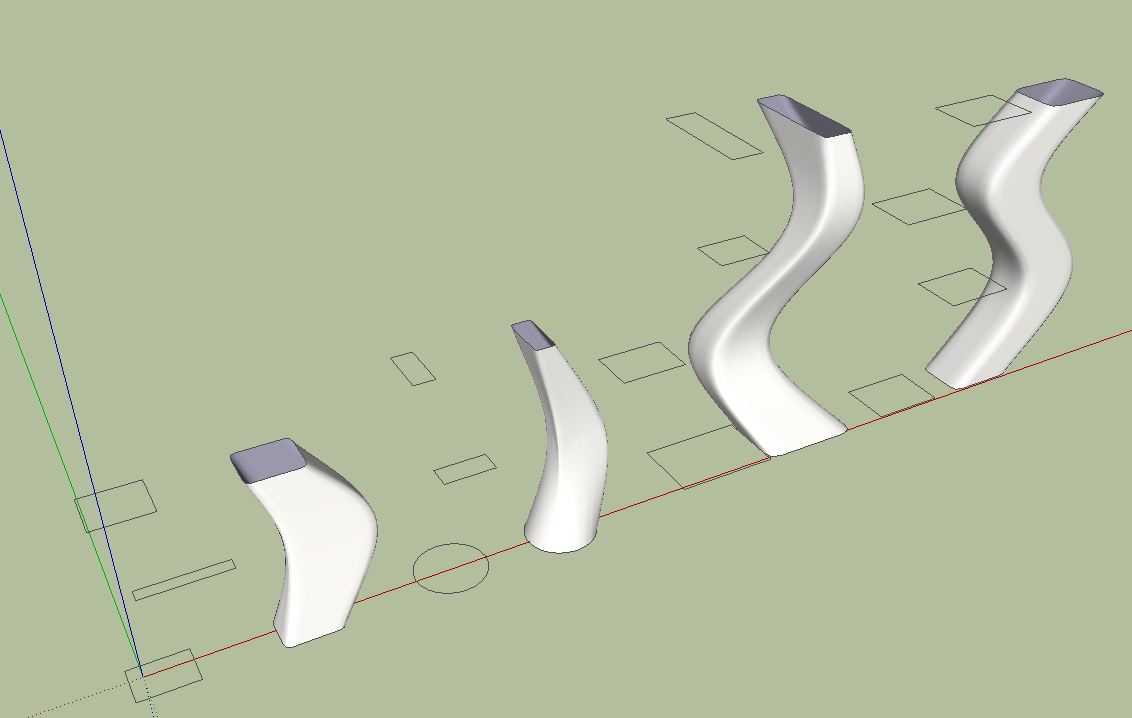
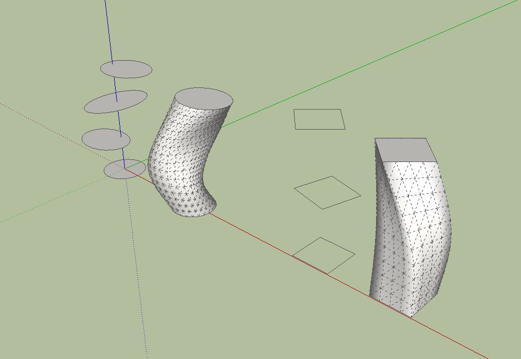
But on the up side i worked the path method see pics YES!


-
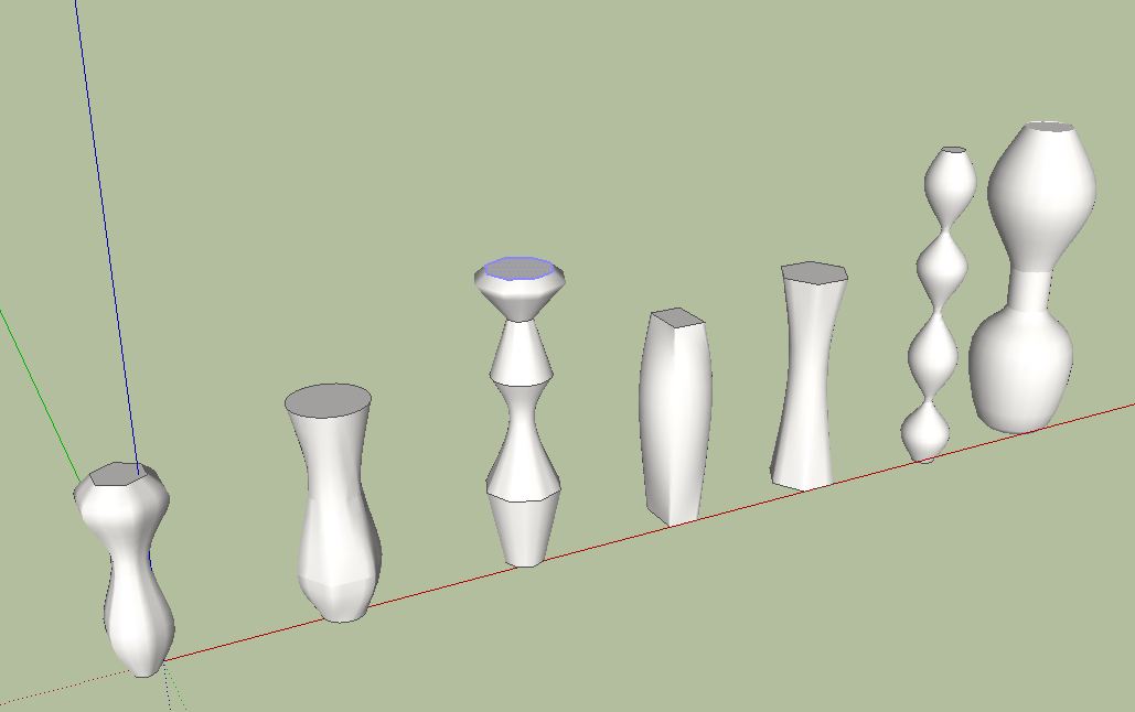
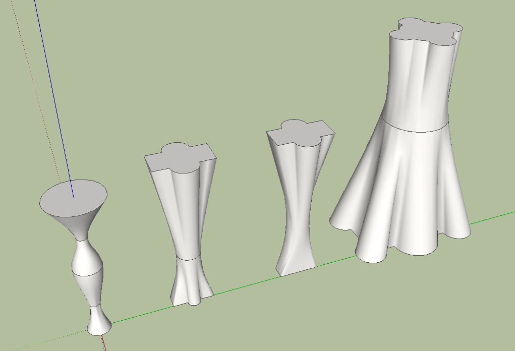
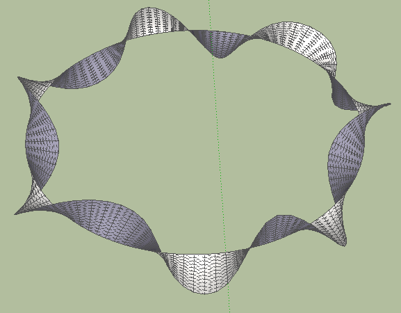
This is a new milestone. I find this tool opens up new design possibilities. The loft tool works very well and easy to understand. Especially because the geometry of the forms can be calculated in advance. Thanks for this wonderful tool.
The last image below is an almost perfect Moebius band. Unfortunately, the last segment is not closed.
-
Fredo
This is already too impressive


-
-
Fredo,
Great impact for SU users in creating 3d models. With yours I am not afraid of creating 3d models from now on..still new!!! Easy and powerful plugins eventhough you give bug warnings but I have not seen any thing so far!!
Genius and generous Fredo -
Thank you Fredo Sir,
you are great
Many Many Many THANK you.I'm shocked man

This plugin is very helpful thank you.
-
@lapx said:
I've tried it as well. Thanks Fredo for such a wonderful. Can you get it to maintain a sharp edge? I noticed it round the corners. Would be nice to have this as an option if available.
These tools do work very well....

The form is auto-smoothed ? You can always select the resultant group and right-click > soften, and set sliders to 0 and all edges will un-smooth/un-soften etc...
or view > hidden_geometry toggle to 'on' and use erase+ctrl+shift to un-soften wiped edges [also remember that erase+ctrl softens wiped edges and erase+shift hides wiped edges - but you must select hidden lines to unhide them using entity info, as there is not erase >> unhide equivalent key-combo...] -
Already a must-have plugin. Thank you Fredo.
-
-
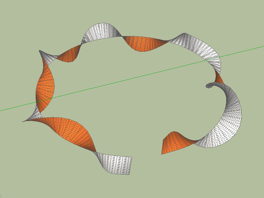
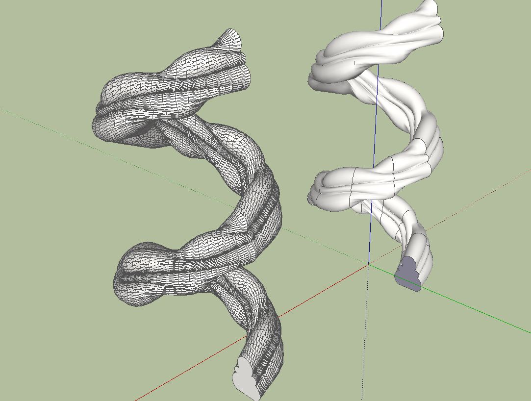
In some forms it comes to interesting but not unanticipated results.
-
@charly2008 said:
In some forms it comes to interesting but not unanticipated results.
Charly,
There are still missing features in Loft along Path, in particular about spiral specific treatments.
But if you can post your model, I can have a look and see if this can be handled.Thanks
Fredo


Advertisement