[Plugin][$] FredoScale - v3.6a - 01 Apr 24
-
hi tig. Yes, I thought the same, but does not work

-
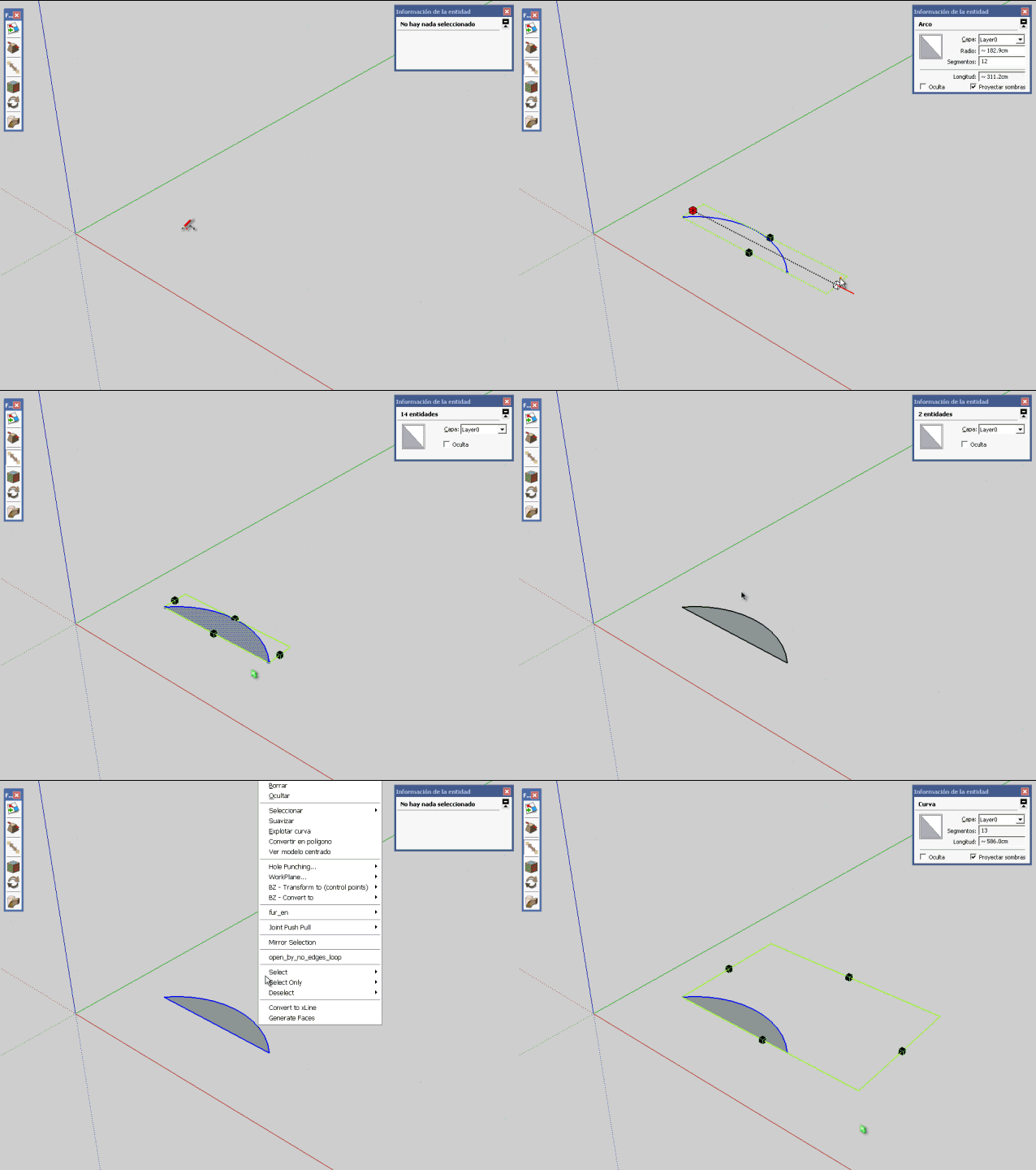
Arcs and Curves applies constraints on transformations unless they are exploded.
-
So Explode them, Scale and then re-Weld into Curves ?
-
@thomthom said:
Arcs and Curves applies constraints on transformations unless they are exploded.
yes?
is strange that all fredoscale tools work well with arc and polylines.
no need to exploit the arcs and polylines -
@diego-rodriguez said:
stretching with orientation of scaling box
small error.
does not work "stretching with orientation of scaling box", with arcs and polylines[attachment=0:lcmr75ft]<!-- ia0 -->Untitled.gif<!-- ia0 -->[/attachment:lcmr75ft]
possible, correct this error?
Diego,
As mentioned in the Doc, FredoScale does not stretch the SU curves. That's just a design choice, because SU does not stretch curves and I would have had to explode the curve, strech the edges and then reconstruct the curves (thios would have been destructive and probably not possible for an interactive visual deformation). It stretches normally if the curve if exploded.
Fredo
-
thank you all for the explanation
-
@diego-rodriguez said:
thank you all for the explanation
Stretch is no more than using the Move tool on the vertices of segment. You can do it manually and FredoScale just automates this process.
As you can notice, all SU Curves move as a whole whatever vertex or edge you select.
Fredo
-
if, extends what do you say.
although my initial question was related to can deform curves, non symmetrical.
But this work can be done manually. only if this work is automatic is more practicalthank you very much again
-
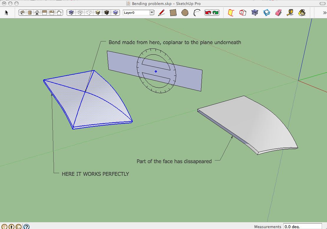
Hi Fredo. As others, I am absolutely amazed about how powerful your tools is. However I found this problem (see attached pic) anytime I try to do a bend which is not coplanar to an existing component face.
In this basic case, I tried a bend using the plane behind the object as a bending plane, whereas I applied the origin onto a random point on the middle of the object's top surface. It always fails, no matter what the object is.
But I also realized that, if I apply the origin on a real point within the component (intersection point, point from an edge of the object), the tool works perfectly.
I post it here, in case you think this is a bug or just the way it works.
Thanks a lot, thumbs up for your great work!


-
If I may suggest: (probably not the problem)
Try scaling the geometry up x10, x100, or some other factor temporarily for the operation, then scaling down by the inverse factor. As you may already know, if the edge distances are sufficiently small, Sketchup/OpenGL cannot close faces, especially when it has to generate new logical edges on a distorted boundary.Like I said, this may not be the problem, just something to rule out.
-
I've use Box Tapering before and it's performed wonderfully (as do all of your amazing plugins), but I'm having a problem now. I'm trying to taper an object, just move the face in a bit. Well, when I move the cursor in the direction I want, nothing happens, and then it snaps to .95. After that I can keep moving it in just as smoothly as you please, but I cannot get it to go anywhere between .95 and 1.00, if I try it just snaps back to 1.00. I've tried typing in the taper I want (somewhere around .98, although I can't be sure yet because I havent' been able to test it), but when I hit enter nothing happens. If I hit enter again it snaps back to 1.00. I've tried many, many times, no luck. Any help would be appreciated.

-
In my recent experience at least with the Fredoscale tool, you can actually type in the specific desired factor eg after you come to rest on 0.95, let up on the mouse button and type in the specific size factor for example 0.98 and hit Enter. Be sure you type in the zero before the .98. Apparently the tool requires this literal input.
There may be some discussion in Fredo's pdf manual on this. I did not check.Try the above and yell back if it works, so others can see.
-
That did it!!!!!
 I've been going nuts for almost 2 days trying to get it to work, and all I had to do was type in 0.98 instead of just .98 Such a small thing, such a big difference! I really appreciate you taking the time to reply, I had just about given up on hearing from anybody about this. Again, thanks!
 -
Glad to be of service.
So many have helped me, or gifted me with amazing tools in this forum, I feel it is necessary for me to pay it forward. -
Your tip came just in the nick of time - I had a gun in one hand, a rusty razor blade in another hand and a samuri sword in the third (yeah, I spent some time around Chernobyl
 ). I owe you a Big Mac. Or a Porsche. Whichever you prefer (although the Big Mac does require less maintenance, gets better mileage and costs a lot less to insure)
  .
. -
Yeah, but the investment all turns to poo.
Edit: And if you gave me a Porsche, I'd just sell it. Either my kids would destroy it, or the maintenance, insurance and worry about dings would destroy me.

-
Well, I could give you a Porsche that's already had the crap beat out of it. Or, I could just toast you at your next wedding

-
@mitcorb said:
In my recent experience at least with the Fredoscale tool, you can actually type in the specific desired factor eg after you come to rest on 0.95, let up on the mouse button and type in the specific size factor for example 0.98 and hit Enter. Be sure you type in the zero before the .98. Apparently the tool requires this literal input.
There may be some discussion in Fredo's pdf manual on this. I did not check.Try the above and yell back if it works, so others can see.
Mitcorb,
Thanks very much.
I fixed the issue and FredoScale (like other plugins) will now accept notation ".98" as equivalent to "0.98". This will also work in formulas (like ".98 + .97")
This will go in a next version of LibFredo6Fred
-
@Fredo: As I said to hellnbak: "Glad to be of service" (in gratitude for your noble gifts to this community).
-
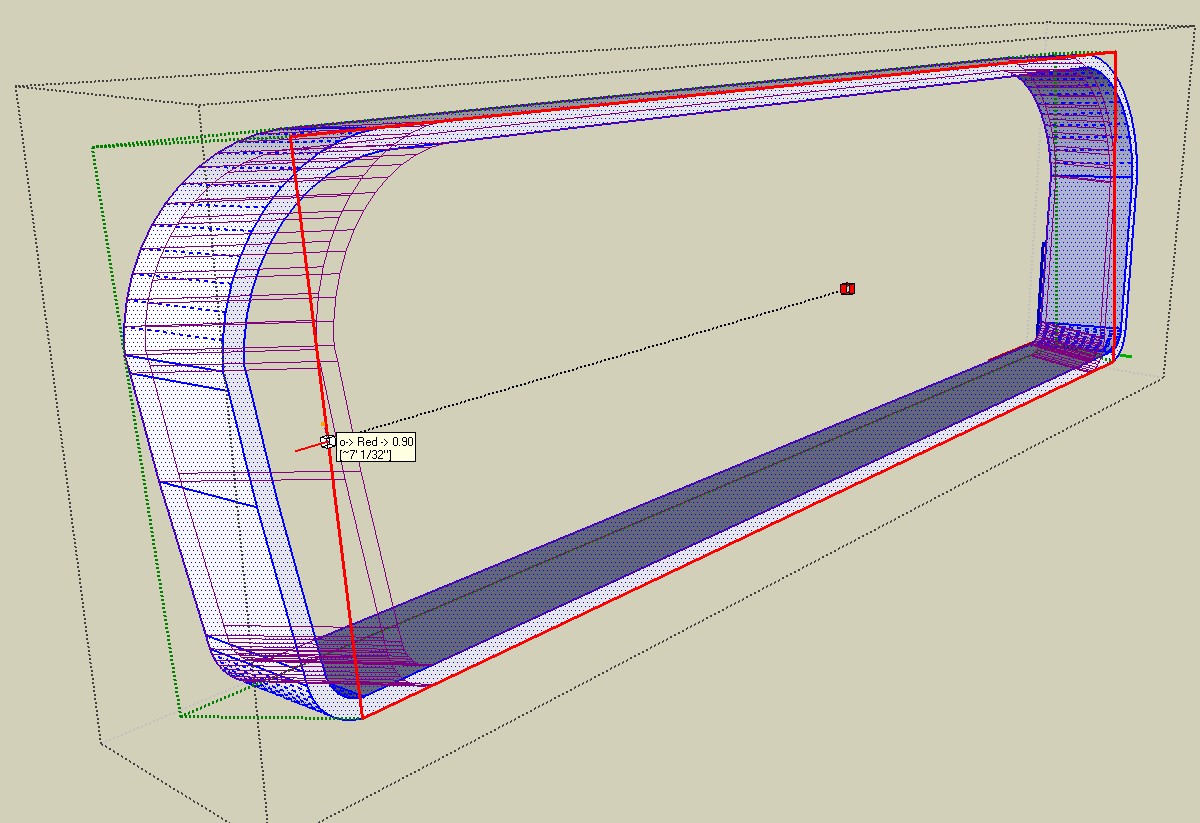
I'm turn in in a project to a CAD shop for fine tuning of model and prototype machining. In the course of revising some turnings, pieces were pulled way out of round— it's so easy to do with the Scale tool, in fact, so hard to keep circular. Not only can you type the percentages into the VCB, but it's incredibly easy to select Option (Command for PC) to scale around center, then hit Control to get the contextual menu that allows you to type in final dimensions by axis, and to understand which axis is which (an arcane SU skill I am nowhere near approaching— first red, last red, it's all so contextual!)
Fredo, thanks so much and so much again! I could have passed it off as is, but now I don't have to look like a dweeb to the CAD designer.
Jim
Advertisement


