Construction & Working Drawings - Discussion
-
I'm new to the forum but was interested in the topic as I have used SketchUp and Layout with some limited success to create scaled construction drawings. Recently I came across some 2D plan and elevation components (and materials) that had a beautiful hand drawn quality to them, ranging from kitchen and bathroom appliances, to outdoor furniture and plants and trees, which were specifically for SketchUp as well as CAD packages. They are from a company called iSymbol at http://www.isymbol.eu and I wondered if anyone has used them as I'm thinking of buying some of the sets to give that 'designer' look to the drawings.
-
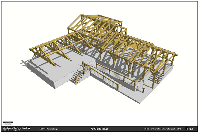
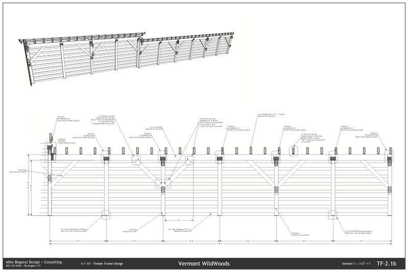
Presentation drawings for upcoming zoning meeting. I'm a timber frame designer - but do plenty of schematic work with my clients, as well as presenting how my work coordinates with others. This particular project I worked the schematic design from scratch, and will see this turned over to a local firm for CD's permits, etc.
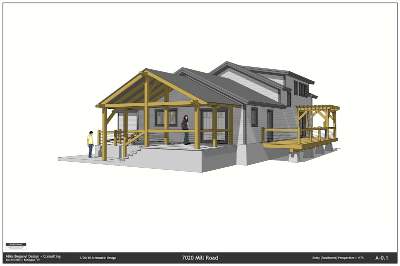
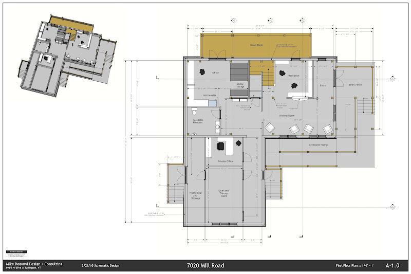
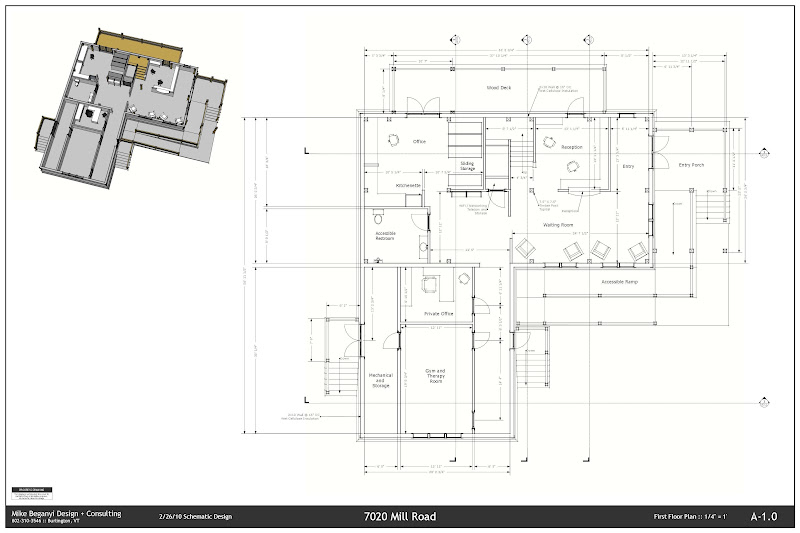
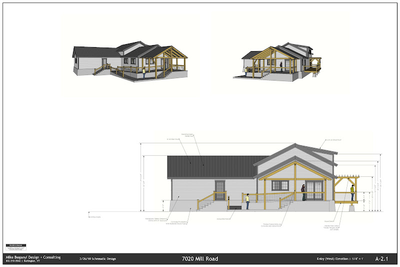
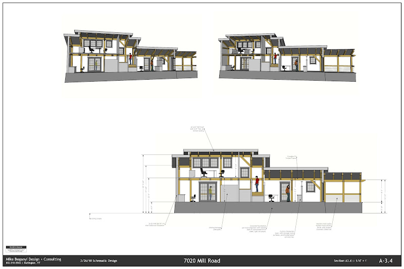
Final set submitted is about 16 sheets. Will also add a few construction detail shots of how the frame interacts with other components. I have the color set, as well as a separate set with a B/W sketch line drawing style - slightly softer than an ACAD drawing, but still crisp for a non color print.
It took a few test plots to see what font sizes I'd like and how my styles would translate to paper. I'm partial to the color versions - but if I were to take this further I'd probably do a mix of color w/without shading and line work drawings.
-
You don't say, so I assume you used Layout to make the presentation drawings. Is that the case?
-
@watkins said:
You don't say, so I assume you used Layout to make the presentation drawings. Is that the case?
are you talking to me?
yes, i did use layout with embedded model(s) to create the tf and building model... -
I don't need to get a building permit in our area (yeah, weird) but I do need decent plans for my contractors to work from. These are they -
http://www.rowledge.org/tim/page19/building/design_assets/Ashling%20Rd.pdf
Entirely SU/LO produced.And here are some sample pages


-
Thanks for all of the interest in this subject.
I finally got my first set to the building department on Monday.
It is, appropriately, a very small house.
When I get more adept at posting, and when my "s" key gets, fixed, I will post it for input.
I currently am working on a two story and man there are still alot of tricks to learn to get any where efficient at this.
Here is an example of this roof cut in issue,
any insight would be most helpful.
aloha
red
and the cover of the PDF file in LayOut for the working drawings.


-
Red- you can cut through the roof - you'll just need to edit that component and get in there and draw it all out... ledgers, plates, rafters, etc. interfacing the walls and floor systems. Build your model like you'd build it in the real world.
I'm doing that now on a project that has 3-4 roof lines all colliding at different levels with floors, overhangs, porches, etc.
-
I know how to cut in a real roof, I just feel it bit too much like work to have to individually push pull each rafter, and the sheathing.
It would seem there is a need for a "slice or cut tool" or ruby, i.e. "anything touching this plane is separated from it's geometry".....
how do you cut a hole in a wall as a simplified example... maybe I should try that...but sep. groups here...
thanks
like to see how your roof comes out, too.
aloha
red -
@redinhawaii said:
I know how to cut in a real roof, I just feel it bit too much like work to have to individually push pull each rafter, and the sheathing.
It would seem there is a need for a "slice or cut tool" or ruby, i.e. "anything touching this plane is separated from it's geometry".....
how do you cut a hole in a wall as a simplified example... maybe I should try that...but sep. groups here...
thanks
like to see how your roof comes out, too.
aloha
redcouple of ways to get there:
if your rafters are all components - then simply drawing a construction line down from the face of the wall tracing it onto a rafter and clipping off the excess will alter all similar rafters. you'll need to go and adjust any thing that is 'unique'.
if they are all different (or not components) - copy the components you want to cut off to the side, leaving the originals in place. create a 'dummy' mass of the second floor - just a big block the same size. copy it over to the same location as the components above. open the various components that you need sliced. triple click once opened to select all geometry. right click. intersect with model. this will draw lines on your component(s) where they intersect that dummy block. delete what is unnecessary. again - any component that is identical will automatically alter... and you'll have to repeat for all components that are unique.
i'm a fan of building my model as i would with hammer and saw out in the field - so i'd go through the trouble of building my roof with repeatable rafter components to minimize work down the road, then cutting them to a ledger or ridge as needed to rest against the mass of the second floor. if you go through the trouble of modeling it correctly - you'll be able to use those details later on for construction documents.
-
Here's a use of LO& SU construction drawings that I hadn't expected.
I'm actually building the house (see above http://forums.sketchucation.com/posting.php?mode=reply&f=12&t=15911#pr234269) right now and during the foundation excavation I had some trouble explaining to the operator where he needed to dig and how deep. I didn't have any serious surveying equipment available so I couldn't do a typical transit layout, taking reference points and marking out angles etc. So I did some quick SU work to fit a set of triangles around the footing perimeters; anyone with a couple of tapes can lay out triangles.
My finished set didn't fit very precisely around the house but did always include every part. I drew up 6 triangles and then used LO to produce a sheet with 6 views, each one adding a new triangle to the one fixed line we had available.
It took a couple of hours working with the digger to convince him that by digging to my lines he would produce a useful hole in the ground but eventually it worked and the resulting hole will soon get its footings.

-
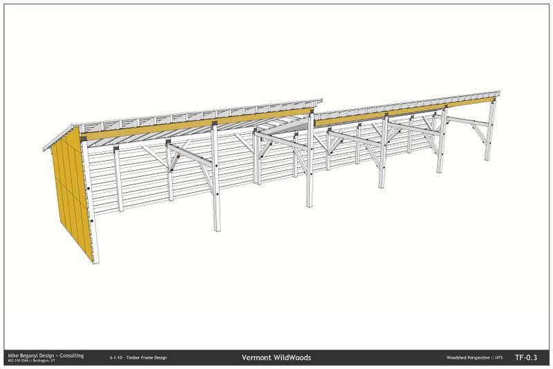
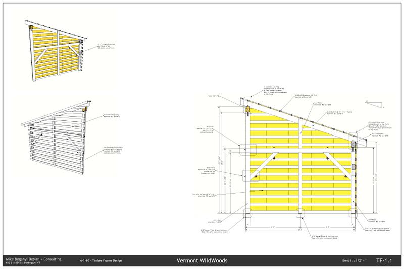
A new project... getting a bit faster. Still wishing for some more intuitive tools, and still wishing LayOut wasn't so damned slow...
-
bmike,
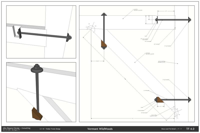
I am really liking these drawings. The 3D bolted connection details are great

-
@unknownuser said:
bmike,
I am really liking these drawings. The 3D bolted connection details are great
thanks...!
-
@dale said:
Another example of this is Atelier Bow Wow.
hoooooly cinnamon buns!!!! this looks awesome, i'm already trying to forget about autocad and this is how i want my drawings to look like
-
Wow that's nice, I like that the bolts are textured and colored so the details are idiot proof. These days you need to make everything as clear as possible because assuming people know what they are doing can be a big and costly mistake. A person experienced in layout can really make a job go much more smoothly and save money too. Those drawings with the bolt details is a perfect example. Thanks for posting it.
-
Hello for all. I,m architect using SU 6 with LO. I'm using SU for the last 11 months, first to develop 3D model to customers. All CD was done in CAD. By now, after seeing LO gallery and earlier posts I decided to include LO to CD. I did prepare many scenes with floor plan, elevations and sections, but when I put scenes in the LO viewports the sections planes are still highlighted. Anyone could help how to fix it?
Thanks in advance.
Riceles Costa
-
Hello. After posting my question I returned to the SU and fix the problem. It is enough use "hide" in each section plane, save the file and update LO file. Very easy.
When my drawings are finished I will post here.
Riceles
-
Hello to all in this thread
I have just uploaded to Google Warehouse my set of Electrical symbols and structural symbols including the Elusive DASHED LINE! To use the electrical symbols just open each component and hide the version you do not want. For the dashed line and arc just scale them to the drawing, edit component and get rid of the very stretched circle. For those who want to fine tune the process of creating dashed lines and get them to the right look for their projects here is the info: painful as it is, for a straight line you must draw a set of equal lines with equal spaces between (or any regular variation, I think mine were 1/4" each) and - here is the key - add a small circle to one end. Then make a component of it and it is scalable.
 For the arc I just drew an arc, exploded it, made a component of it, and hid every other segment in edit mode. It too is scalable.
After digesting every word in this forum topic it is time to give back to you all. At least I hope this is an original idea or I will feel real stupid
 the URL: http://sketchup.google.com/3dwarehouse/cldetails?mid=ead79f519f67b4c28fb37abf337da9ec&ct=mdcc&prevstart=0
Thank you all for the great info.
Klog -
Hi Klog,
Thanks for those! I am not in this trade but I understand it will be extremely useful for some people!
-
I am very much impressed with the capabilities of SU... but I find CAD applications more easy and the results are more perfect the 3D view is also more accurate without containing any mistakes and it is trustworthy. I have been using CAD applications for about more than 2 years and I'm loving it
 but there can be some more things that can be done by integrating both CAD applications and SU, like the use of DataCAD 12, import the SU features and then have DataCAD generate 2D elevation drawings. It can take a few minutes, but still quicker than recreating them from scratch, and cleaner than importing a dwg file from SU. So it can be more useful that just using a single software
Hello! It looks like you're interested in this conversation, but you don't have an account yet.
Getting fed up of having to scroll through the same posts each visit? When you register for an account, you'll always come back to exactly where you were before, and choose to be notified of new replies (either via email, or push notification). You'll also be able to save bookmarks and upvote posts to show your appreciation to other community members.
With your input, this post could be even better 💗
Register Login


Advertisement