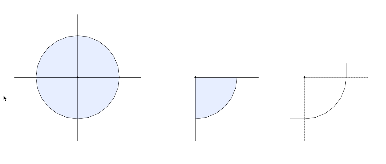
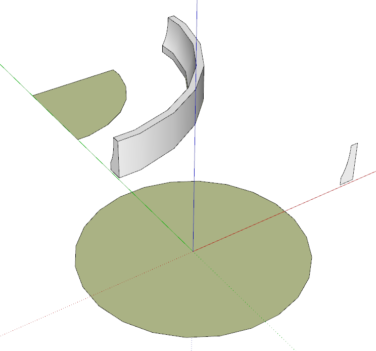
Circle issue maybe good tip or need better tip
-
It is the way the FollowMe tool behaves. It follows the angle of the edge when extruding.
Rather than following a 1/4 do the whole circle. Then remove the unwanted.
-

 ... a good tip I think - I also try to finish orthogonally to the main axes in such situations and I also hadn't had a better idea so far
Usually I add ortogonal lines to the path to end up in the desired ortogonal shape and push-pull then back to the needed axes...

-
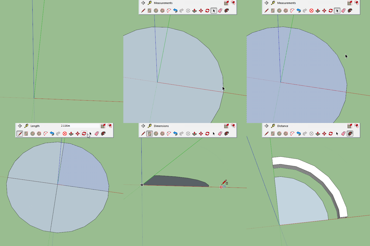
No matter how many segments in your circle, rotate by half a segment before cutting the circle in half. This will ensure the follow me finishes perpendicular to the first and last segments.
This is the reason I have asked a couple of times for the ctrl modifier to work the same on circles as it does on polygons. They added to rectangles but still not circles. -
@box said:
No matter how many segments in your circle, rotate by half a segment before cutting the circle in half. This will ensure the follow me finishes perpendicular to the first and last segments.
This is the reason I have asked a couple of times for the ctrl modifier to work the same on circles as it does on polygons. They added to rectangles but still not circles.could you please show me some demo??
I don't fully understand this part---> 'rotate by half a segment'
if this is better tip to solve my issue, I really want to learn your solution!
-
On phone just now so will demo when back at PC.
-
Here you go, does this make it clearer?

-
@box said:
Here you go, does this make it clearer?
yesyes. thanx for the demo!
It's pretty much same method only difference was that I typed degrees
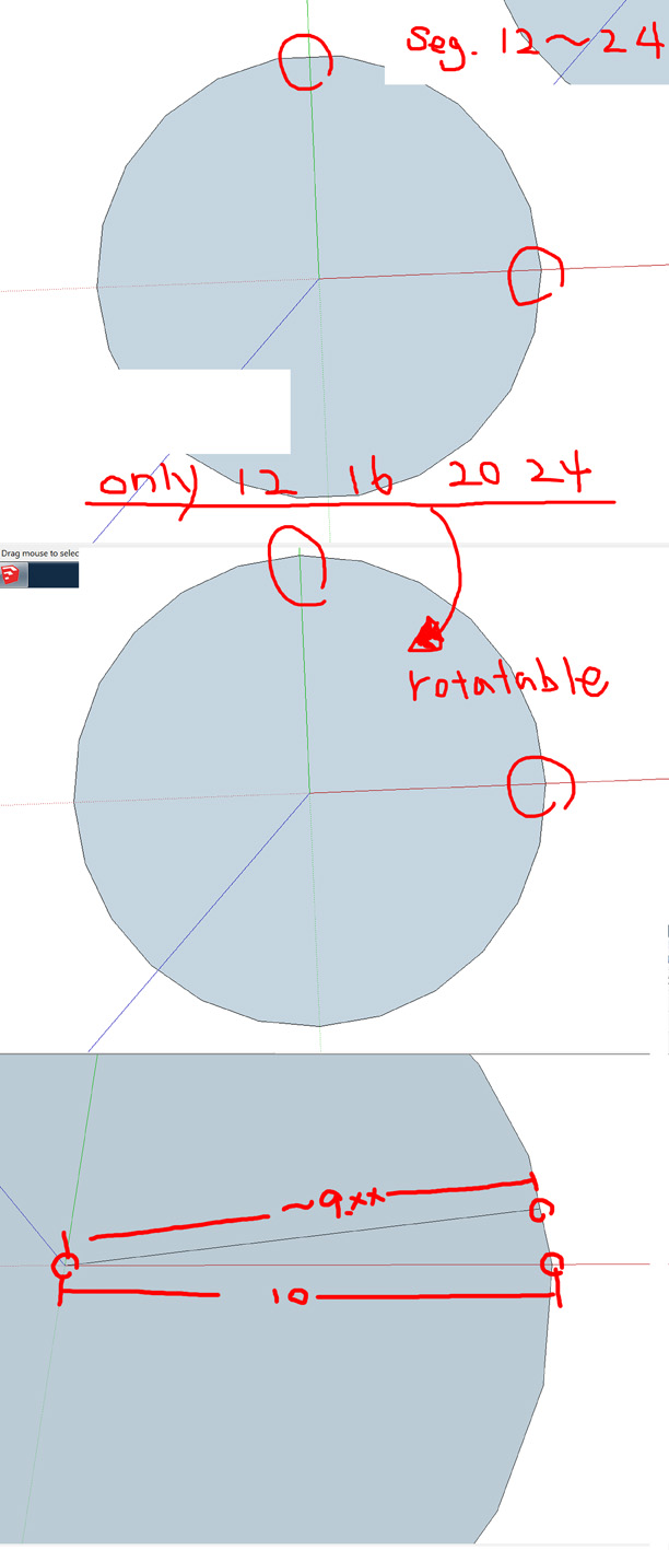
thanx again! It is much better and easierby the way I found number of seg. was also considerable to follow your instruction
as you see in the image below
but after rotate a circle, I'm still not comfy that I got '~x.xx'......
no precise number of length. I don't like '~' in front of my measurement = =;thanx!

-

 and again a clever Box Gif - thanks for it!
And such a simple trick that I would never have thought of


-
@dohyungkim said:
by the way I found number of seg. was also considerable to follow your instruction
Yes you are right about that, my mistake for not being clearer.
Circles are best drawn with the number of segments being multiples of 4, this makes the cardinal points easier to find. So with that in mind rotation also works.@dohyungkim said:
but after rotate a circle, I'm still not comfy that I got '~x.xx'......
no precise number of length. I don't like '~' in front of my measurement = =;If you are getting a Tilde in your measurements it suggests that you have your Units set too course. Adjust the Precision in Model info to something more appropriate for the model you are working on.
-
@dohyungkim said:
@box said:
but after rotate a circle, I'm still not comfy that I got '~x.xx'......
no precise number of length. I don't like '~' in front of my measurement = =;thanx!
Because SketchUp represents a circle as an inset polygon, only the vertex points are at the true radius of the circle. The midpoint of each segment is actually closer to the center and will usually not be any distance that the UI can represent exactly, so you get the '~'. Sometimes you can eliminate the '~' by increasing the precision of the units displayed, but this will just make the display correct (e.g. 10.35554 instead of ~10.36) it won't cause it to change to the true radius.
There are a few ways to get dimension to be the exact size of the theoretical circle.
If you activate the dimension tool and click on the circle as the start, the tool will create a dimension showing the true diameter of the circle no matter where on the circle you clicked. You can right-click this dimension and select the Type item to change it to a radius dimension. A radius dimension has a different look than other dimensions, more like a leader text with the letter 'R' preceding the radius. This might not provide the appearance you want.
If you click first at the center of the circle and then at one of the vertices, you can create a dimension that shows the actual radius of the circle. Because this dimension is "associated" with the vertex, it will rotate along with the circle when you rotate the circle, remaining true instead of changing to the distance to a midpoint. This has the disadvantage that the dimension's leader lines will be askew from the model axes by the amount you rotated the circle.
Finally, you can fudge the dimension by editing its text to show the value you want. Activate the dimension tool, right-click on the dimension and choose "Edit text". Obviously, this has the downside that the displayed dimension isn't the actual distance to the midpoint, which could cause errors later. It will display in red in SketchUp to remind you that it isn't associated with an object in the model.
-
It's also worth noting that the path and the profile don't have to touch. In this case, it means the radius of the path circle isn't especially critical.

Advertisement


