[Plugin][$] FredoScale - v3.6a - 01 Apr 24


-
NEW RELEASE: FredoScale v2.5b - 15 Sep 13
FredoScale 2.5b fixes a bug preventing language translations to load.
FredoScale 2.5 requires LibFredo6 5.2 or higher.
See main post of this thread for Download.
Fredo
-
@fredo6 said:
NEW RELEASE: FredoScale v2.5b - 15 Sep 13
FredoScale 2.5b fixes a bug preventing language translations to load.
FredoScale 2.5 requires LibFredo6 5.2 or higher.
See main post of this thread for Download.
Fredo
After the update:

-
-
-
@dedmin said:
:thumb:

BTW, did You see this:
http://sketchucation.com/forums/viewtopic.php?f=323&t=46473&start=90
http://sketchucation.com/forums/viewtopic.php?f=323&t=54176-
For Curvizard Edge Prop, I had found the bug actually but forgot to republish
-
For BezierSpline, I have to investigate. This is old code and the tooltip may not reflect the correct alignment
Fredo
-
-
Thank timely updates, thank you

-
Thank you, thank you, thank you....is very good.
-
Hi Fredo,
Is it normal dimensions differences in?


-
@enigmatic said:
Hi Fredo,
Is it normal dimensions differences in?
Maybe some rounding ... bug? I'm guessing it rounds in all situations, not considering the units used (and number of decimals) ?
-
Bonjour,
J'utilise régulièrement FredoScale et Curviloft et je viens de télécharger Joint Push/Pull. Je voudrais te faire une petite donation (symbolique) mais je ne veux pas passer par PayPal. Je voudrais t'envoyer un mail mais je n'ai pas ton adresse. Le mien est samothrace41 @ yahoo.fr
A+
Sylvie -
I don't understand if this plugin can help me.
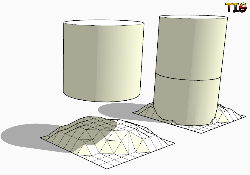
I have a non-planar surface close to a cylindrical surface; I want to extrude a region of the non-planar surface up to the cylinder to create a solid 3d joint between cylinder and the non-planar surface.
Can I use this plugin, or do I need another one?
-
@jumpjack said:
I don't understand if this plugin can help me.
I have a non-planar surface close to a cylindrical surface; I want to extrude a region of the non-planar surface up to the cylinder to create a solid 3d joint between cylinder and the non-planar surface.
Can I use this plugin, or do I need another one?
If you want to project the bottom face of the cylinder down onto the surface then look at my ExtrudeEdgesByVector[ToObject] tool.
Edit the cylinder [group?] and copy the bottom face.
Exit the edit and use Edit>PlaceInPlace.
Select the face-copy [double-click].
Activate EEby..Object tool and pull a vertical [blue] vector down through your surface.
The face is extruded and stops on the surface...
With some finely divided surfaces the 'auto-trim' might fail, so in that case extrude through and manually intersect/delete parts.. With the simple 'toVector' version of the tool it extrudes through the surface - in that case then edit the grouped extrusion and Select its geometry and then use Intersect with Model: now Select [by fence] for the unwanted lower geometry and delete it.
-
Thanks!
-
excellent
your amazing tools are very useful
thank you very mach fredo -
NEW RELEASE: FredoScale v2.6a - 27 Nov 13
FredoScale 2.6a is a release for future Sketchup compatibility. It is advised to upgrade even if there are no functional changes.
See main post of this thread for Download.
Fredo
-
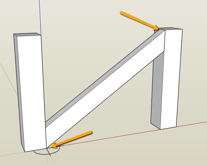
I recall a while ago the question being asked how to rotate accurately say a cross brace in a fence [see below]
I'm drawing a louvre window and want my blades to be angled in 3D to accept shadowing but only want to open the blades to the point where the top of the blade is in the same horizontal line as the bottom of the blade above. This way in elevation I achieve a clean horizontal section as well as seeing depth in shadow.
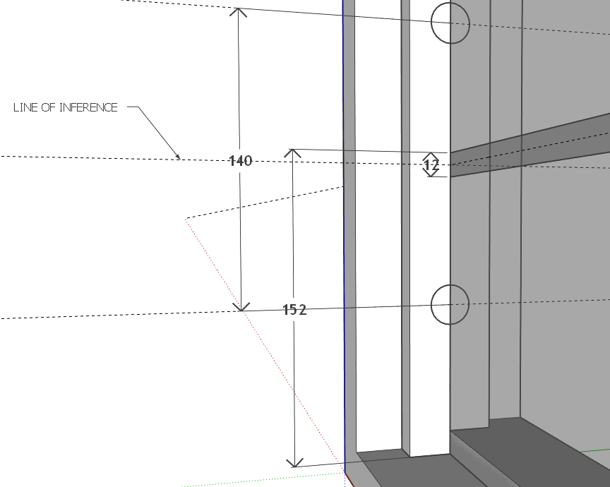
For the life of me I have been trying to rotate the lourve blades using Fredoscale rotate but do not have the option to inference to the centre of the louvre blade overlap... [middle of the 12mm overlap]
I've attached the skippy to let you see what I'm doing as well as a short video.
I expect it is something really simple that will make me look like a goose [holidays will do that...
-
Andrew, try this:
Draw a short line segment along that horizontal guideline in the vicinity of where the corner of the bottom louver should be. You can then use Rotation by Selection and Angle of Plane (the red rotate icon) to rotate and snap to the line.

Select the bottom louver.
Get the red Rotate tool from Fredoscale.
Click on the center of rotation.
Click on the top corner of the louver.
Click on the top corner again.
Move the cursor over toward the line bringing the louver corner with it.
When the line turns orange, click again to set the corner on the line.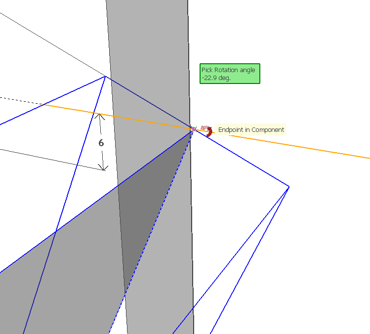
Do not repeat for the other louvers. Delete them and copy the rotated one up and make a linear array.
Delete the little short line when you've finished with it.
-
I can see what you've done here, Dave. THANKS!!!
I was going into the component and trying to inference from within.....
YOU DA MAN!!
-
Thank you.
I can see the reason for opening the component for editing because all of them would rotate at the same time. I expect you could still do that with the line but I think I'd leave the component as is and rotate the whole thing.
-
Fredo,
First of all thanks for this and all your wondeful plugins. There can't be thank enough for this contribution but I've came here bragging with an issue I've come across with Box Scaling to Target.
It is a very useful and natural way of scaling things in Sketcbup and it replaced my S key long time ago. However, today, a very simple operation gave me an unexpected result and I never seen this before. Probably it's because I hadn't noticed it or because of some setting I have changed that I'm not finding right now.
I don't know where an I failing but please take a look at this:
")

 instead of (0.75m, 0.8m). This also happens when trying to snap to an existing geometry (like that guide there).")

.")
Is there anyway I can override the snapping factor and get on with only the distance on VCB?
Thanks and best regards,
JQL
Hello! It looks like you're interested in this conversation, but you don't have an account yet.
Getting fed up of having to scroll through the same posts each visit? When you register for an account, you'll always come back to exactly where you were before, and choose to be notified of new replies (either via email, or push notification). You'll also be able to save bookmarks and upvote posts to show your appreciation to other community members.
With your input, this post could be even better 💗
Register Login


Advertisement