Strange behaviour of SU when molding a door
-
Hi everybody,
I'm experiencing a strange behaviour of SketchUp. I made up my mind to a possible reason for that but I'd like to submit the question to your experience, to see if I'm wrong or not.
I'm trying to mold the internal side of a door. This door is made of four components and I want the molding to run seamlessly all around the internal path.
What I did was to run the Follow Me tool inside every component, scaled up by 100 times. I did several samples, trying different arc segments. With low segment arcs the molding doesn't match internally, with high segment arcs the molding match gets better.
But here's the main issue: when I scale down the component to normal size, everything runs well, I mean the component maintains its geometry intact and the unmatching is almost invisible. When I save the file, SketchUp seems to be unable to preserve that scaled down geometry and shows me the compoment with missing faces. Obviously, the more segments the arc has, the more are the missing faces.
I suppose that in this case SketchUp is unable to save all those tiny segments in its memory as he was able to do after the initial scale down. I also suppose that the problem is that externally the Follow Me tool "follows" a curve, but internally there is a 90° angle and that causes the mismatch that is partially cured incresing the segments of the arc.
What do you suggest? Do I have to accept a mismatch staying with low segments arcs or is there a better method to accomplish the task?
Luca
-
Hi Luca,
You should be able to eliminate the mismatch altogether. My approach would be to profile the top rail separately and extend the path out off the ends similar to the way I did the stopped chamfers on the hayrake table, which I'm sure you remember.
 As soon as I finish up the project I'm working on, I'll make up something to show you.
Ciao,
Dave
-
Hi Dave,
this is exactly what I did and the match is fine on the external path, but not internally. I also tried to run the follow me on the complete loop and paste it in place separately in every component but the result is the same.
Luca
-
I had another thought about how to approach this but I have to get this other project finished first.
-
@brandy20 said:
Hi everybody,
I'm experiencing a strange behaviour of SketchUp. I made up my mind to a possible reason for that but I'd like to submit the question to your experience, to see if I'm wrong or not.
I'm trying to mold the internal side of a door. This door is made of four components and I want the molding to run seamlessly all around the internal path.
Luca
Luca,
I'll offer a different solution than what I expect Dave may be working on.If using SU Pro you can use the solid tool function "subtract" to accomplish what you seek.
In attached .skp I made a component profile (solid) and subtracted it from each of your door components (also solids).
Once the solid profile is in place, copy it to SU clipboard, then subtract from the selected component, then paste in place & repeat for the remaining components.
see below .skp
Best,
Charlie
-
Charlie, that's one option I was going to suggest. You beat me to it. I was also going to suggest using Intersect and deleting the waste for those who don't have access to the Solid Tools.
-
I was going to offer a suggestion, but then I realized something - I haven't a clue

-
%(#BF00FF)[<Postby brandy20 on Sun Oct 30, 2011 6:17 pm
Hi Dave,this is exactly what I did and the match is fine on the external path, but not internally. I also tried to run the follow me on the complete loop and paste it in place separately in every component but the result is the same.>]
Luca
Brandy FYI
The way the follow me tool works is it's projecting along sequential vectors define by the path you select. At the very first step, if the surface is not perpendicular, then the surface is basically reduced in size by the cosine of the angular error. To get the size you want make sure this criteria is followed=> it will be in error all the way around however.
Because of this projection and my assumption were you were trying to do the extrusion on each component separately (not with standing your above comment) you are not giving the program enough info to allow for correct corner formation and thus the errors. I exploded your 1000 scale model and did the loop approach and it worked just fine. I then scaled down by 1/100 and then 1/10 with the first step ok but the second was not very good. I then used the tape tool to resize to your .568 mm height and that worked fine. Scaling up more than back down ( based on previous postings ) will probably work but did not try that.
Why so small to start with?? ~ 1mm is the break point
Just some thoughts -
First, thanks to everybody for taking the time to get inside the problem and answer me.
I'll try to answer you in order of appearance

Charlie: I only have the pro for v7. My v8 is free so I don't have Solid Tools. Anyway I took a look to your file and the path you used for the molding is not the same I used. Look at the corners, I have a curve and you just used two segments. Try with my curve and I suppose you will have my results, since ST are an evoluted way of telling SketchUp to intersect geometries. The problem lies in THAT curve because SU tries to perform that curve also on the internal side of the molding but has to create extra geometry that is partially compensated by very short segment when you scale up the model by 1000 times.
Mac1: I think you really got the point of what I mean. SU creates sequential vectors following the path, that's why I'm experiencing the problem. I didn't try to resize with the tape tool, I'll do it soon. The measures are 568mm by 328mm. Where did you find .568? It's not a micro door...
Eliminating the arc and drawing two segments at the corners would be an alternative but I wanted to draw that door as it was routed in the shop. And then, another question is still open: why I can accomplish the task I want, scaling up the model, doing the Follow Me and scaling back with no problems BUT when I save the model or the components SU looses some faces? If SU can't handle very short segments it should start loosing faces just after the scale down.

Should I think of it as a limit of SketchUp and change the molding path?
Luca
-
@brandy20 said:
First, thanks to everybody for taking the time to get inside the problem and answer me.
I'll try to answer you in order of appearance
@brandy20 said:
Charlie: I only have the pro for v7. My v8 is free so I don't have Solid Tools. Anyway I took a look to your file and the path you used for the molding is not the same I used. Look at the corners, I have a curve and you just used two segments. Try with my curve and I suppose you will have my results, since ST are an evoluted way of telling SketchUp to intersect geometries. The problem lies in THAT curve because SU tries to perform that curve also on the internal side of the molding but has to create extra geometry that is partially compensated by very short segment when you scale up the model by 1000 times. Luca
I read/understood your initial post to mean internal path.
I'll have another look see.
Charlie@brandy20 said:
Eliminating the arc and drawing two segments at the corners would be an alternative but I wanted to draw that door as it was routed in the shop. And then, another question is still open: why I can accomplish the task I want, scaling up the model, doing the Follow Me and scaling back with no problems BUT when I save the model or the components SU looses some faces? If SU can't handle very short segments it should start loosing faces just after the scale down.
LucaI thought I saw some small line fragments in your component corners, I suspect this is where looses faces.
Charlie
-
@brandy20 said:
Look at the corners, I have a curve and you just used two segments. Try with my curve and I suppose you will have my results, since ST are an evoluted way of telling SketchUp to intersect geometries. The problem lies in THAT curve because SU tries to perform that curve also on the internal side of the molding but has to create extra geometry that is partially compensated by very short segment when you scale up the model by 1000 times.
the problem (at least as i see it) lies in using the follow-me tool.. honestly, follow-me is basically junk in sketchup when accuracy is of concern.. the same goes for the offset tool and basically any operation that deals with radii.. the fact that arcs are made of segments in sketchup is the basis of the problem and sketchup isn't smart enough to be aware of a true perpendicular to a curved line.. instead, it thinks perpendicular to a curve really means perpendicular to a segment of said curve (which aren't the same thing)
i'd suggest you use TIG's lathe tool from his extrude edges suite to build the profile in sections then join them together instead of trying to do something with follow-me.. see attached skp.....
lathe tool found here:
http://forums.sketchucation.com/viewtopic.php?t=25362 -
@brandy20 said:
First, thanks to everybody for taking the time to get inside the problem and answer me.
I'll try to answer you in order of appearance
Charlie: I only have the pro for v7. My v8 is free so I don't have Solid Tools. Anyway I took a look to your file and the path you used for the molding is not the same I used. Look at the corners, I have a curve and you just used two segments. Try with my curve and I suppose you will have my results, since ST are an evoluted way of telling SketchUp to intersect geometries. The problem lies in THAT curve because SU tries to perform that curve also on the internal side of the molding but has to create extra geometry that is partially compensated by very short segment when you scale up the model by 1000 times.
Mac1: I think you really got the point of what I mean. SU creates sequential vectors following the path, that's why I'm experiencing the problem. I didn't try to resize with the tape tool, I'll do it soon. The measures are 568mm by 328mm. Where did you find .568? It's not a micro door...
@unknownuser said:
I used your first scene and must have scaled by 1/1000 vs 1/100.
 Save and reopen works ok. Do not think you need to eliminate the arc. Under stand even though your model is 5.68 mm tall when you do the follow me there are areas where that dimension is much smaller. I am not exactly clear on your work flow and the associated problems. Am I correct in the assumption for some case you were doing each component on a stand alone basis? You want to do the follow me around the whole perimeter at once so the boundary values are correct to let the follow tool do its thing or as Dave indicted above you can establish the correct boundary values by extension. Try by scaling up by larger value then back down but boundary values must still be maintained if you do a component at a time.
The issue of scale up , scale down ok but close/open is not I have no answer for. Pure guess it could be a graphics issue. Do not use any type of length snapping
@unknownuser said:Eliminating the arc and drawing two segments at the corners would be an alternative but I wanted to draw that door as it was routed in the shop. And then, another question is still open: why I can accomplish the task I want, scaling up the model, doing the Follow Me and scaling back with no problems BUT when I save the model or the components SU looses some faces? If SU can't handle very short segments it should start loosing faces just after the scale down.
Should I think of it as a limit of SketchUp and change the molding path?
Luca
-
Luca,
Others have described better than I could, what/why.Attached shows how I might overcome SU Follow Me.
Basically make the "tool" that would perform the cutting in real worl.
Orient the arc segments to the rail/stile. and "quarter it".
Intersect the "tool" with the problem corners and follow me to complete.Or create a solid using the same "quarter" of the tool, and subtract from ea. component.
Best,
Charlie
-
Brandy20
Another comment. Make the model like one will typically build the door. Assemble the rail and stiles first and then do the moulding cut just like you would with a real door. It seems to me cutting the individual rail and stile components would be difficult and dangerous if possible at all. If you do it this way the follow tool will work very nicely. -
@mac1 said:
Brandy20
Another comment. Make the model like one will typically build the door. Assemble the rail and stiles first and then do the moulding cut just like you would with a real door. It seems to me cutting the individual rail and stile components would be difficult and dangerous if possible at all. If you do it this way the follow tool will work very nicely.actually, it won't work very nicely.. i'm telling you, follow-me is junk.. (see attached .skp)
-
First, thank you to all for this interesting problem analysis.
If you do that in your shop, in reality the corner will appear a little different as what Jeff describe.
Using the router after assembling the frame is effectively the way to go.
But you'll use a router bit with a bearing at the bottom, having a special radius.
How would you represent this in SU ?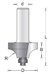
-
Hi folks.
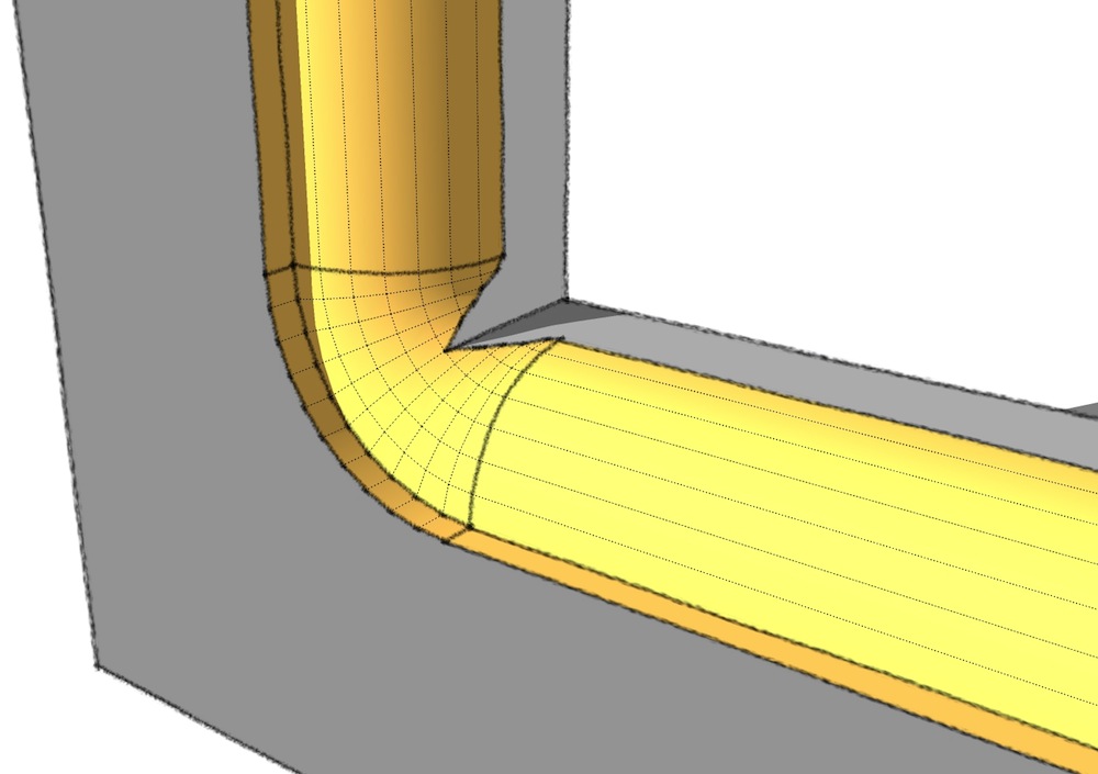
The Follow Me tool, when used to extrude a profile around a curved path may produce these problem if you extrude the profile inside the path. If you use it outside, the problem don't show.
However, with some combination of arc radiuses and segmentation for the path, it is possible to get good result, even if the profile is inside the path.
See all the scenes of the attached SU file for ideas.
-
@jean-franco said:
First, thank you to all for this interesting problem analysis.
If you do that in your shop, in reality the corner will appear a little different as what Jeff describe.
Using the router after assembling the frame is effectively the way to go.
But you'll use a router bit with a bearing at the bottom, having a special radius.
How would you represent this in SU ?if you used one of those bits to cut the profile after assembly, it wouldn't turn out too sweet..
-
This discussion is getting more and more interesting

I found Jeff and Charlie's approaches very clever, even if I still haven't tried Charlie's at the top of the door, where the molding should also be curved.
I knew about TIG's Extrusion Tools but never found an application for me with the Lathe tool. So I spent some time in getting to grips with it. I think it is a very good tool but I'm experiencing some troubles with the angles of the curved top molding. After having extruded the two corners at about 79,371° (
 )I found the centre of rotation of the arc (Point a centre) and tried to extrude every section corresponding to each segment of the arc. The arc angle is about 21.258°, there are 12 segments for the arc, so every extrusion should measure 1.7715°. But I can only write 3 values after comma, this means adding some more imprecision to the angle. After three extrusions I notice that the segment of the extruded profile is not following the segment of the arc. The difference is very small but, after 12 extrusions the difference increases and this causes (at least to me) problems when intersecting geometries to clean up the molding.
Where am I wrong?
Jean (Lemire), thank you for your hints, but as far as I can see, your example ends up with rounded corners also internally, where they should be squared instead. Unless I didn't go deep enough in your example, I don't think it's the right solution.
Luca
-
We have to agree to disagree. Follow me has been around for some time and as with many things they get over taken by progress. To call it junk I think does a disservice to the creator. If the model is made carefully it works fine. As posted many times you must scale up by a relative large number for that to happen. More than the OP.
I have posted many times there is no tangent in SU by the mathematical definition ( unless you think a straight line is appropriate for consideration.). The designers have come up with an approach and if you don't like that why use it?
TIG's tools are very nice because they are adaptive in the sense a relative fixed geo is not required.
Hello! It looks like you're interested in this conversation, but you don't have an account yet.
Getting fed up of having to scroll through the same posts each visit? When you register for an account, you'll always come back to exactly where you were before, and choose to be notified of new replies (either via email, or push notification). You'll also be able to save bookmarks and upvote posts to show your appreciation to other community members.
With your input, this post could be even better 💗
Register Login


Advertisement