Construction & Working Drawings - Discussion
-
Daniel, Currently, I design and build my models with a Cad application then Dxf them to SU for visualization and presentation. The original model is assembled from blocks that translate as SU components. All changes to blocks are via the Cad application, that are then individually Dxf's to SU (minimizes redo work to the block/component in SU). In my case, the elevations are complete before the model is ported.
Have you ever used SU's scenes to create 2d elevations (parallel projection, aligned view) 2 Dxf for use in your Cad program? What are your pro and cons on this? Thanks.
-
My workflow is slightly different. We start with a plan, either in CAD or sketched out, and then I usually do the model. I have in the past imported the CAD plan into SU, but I found there was too much clean-up (especially if the plan was drawn by others), so it's quicker to start modeling from scratch. The majority of my models are just the exterior, anyway. From the model, I create the CAD elevations.
I have in the past created orthogonal views and then exported dwg files, and then imported them into DataCAD, but I found there was always a lot of clean-up to do. Any line touched or crossed by another line would be broken. On a railing with vertical pickets, for instance, the line for the top rail would be broken at each picket, so I would have a series of short lines instead of one long line.
But with the latest version of DataCAD I can import the model directly into SU. It comes in as a wire frame. I set the view in DataCAD, tell it to perform a hidden line removal and to save the image in a separate layer, and then I have a 2D elevation without broken lines. All I have to do is change the colors of the lines to match our office standards. This is much quicker than drawing them from scratch or cleaning up a dwg file, and I much rather spend the time modeling with SU.
I can also export a DataCAD file as a SU model, but haven't found a use for that, yet (I suppose if I wanted to import a CAD plan or other drawing into SU, that is how I would do it, now). -
I got pretty excited with LO beta and tried to make it work, I struggled with it for many projects then stoped when my support tickets when unanswered. The release version is more stable but when I saw it still lacked dimensioning I just gave up on it. I would instantly embrace it for shop drawings and simple plans if it could dimension since I am still doing quite a bit of design in SU. For now it just has really limited use in my work world
 .
. -
I've been using Layout for woodworking plans lately and although there are a few things I wish it had related to text handling, I think it works fine. I place dimensions in SketchUp and create callouts and other text in LO. One thing that I found is that I end up with dimensions at 6 pt. in SketchUp. They are almost impossible for me to read on my screen in SU but work out just fine in LO and in the exported PDF.
-
Dave, I am very interested in exploring the new possibilities in LayOut. You are right! Its best to accept what Layout does not offer and get on with what it does.
Mike
-
Mike, it could be that because I'm not familiar with other programs such as Illustrator that are designed for doing presentation documents and the like, I don't find the limitations of Layout to be all that limiting. I see a huge benefit in having the SketchUp model dynamically linked to the document. That has been a big bonus.
Last Novemeber I did a plan in SketchUp for a small cabinet or bedside table. The client chose to use Illustrator or something for the document. I created scenes in SU and sent the file. They exported JPGs for use in the document. There were several revisions to the model which I got into SketchUp but the scenes didn't get replaced in the document and proofing didn't catch the errors before it got out. The plan was finally updated yesterday.
Last week I delivered a workbench plan to the same client but I did the entire thing in Layout. Again, there were several rounds of revisions to model but they were all incorporated in the PDF this time. If there are any erors, at least there's consistency between the model and the plan. Both of them are to be offered for sale as a package by the client.
-
@dave r said:
I've been using Layout for woodworking plans lately and although there are a few things I wish it had related to text handling, I think it works fine. I place dimensions in SketchUp and create callouts and other text in LO. One thing that I found is that I end up with dimensions at 6 pt. in SketchUp. They are almost impossible for me to read on my screen in SU but work out just fine in LO and in the exported PDF.
Dave,
Great point about the font, I have found that setting the font to inches is even more predictable/consistent.
I recently did kitchen cabinetry & vanity elevations this way @ 1/2" = 1'.
My SU dimension font was set to 3"....I exported out of layout to .pdf.....looked great.C
-
Hi everyone
As an answer to WBARCH wish
Being retired and doing woodworking as a hobby here is an example of what I obtain using Sketchup and Layout and exporting to PDF
http://cid-ef5ebd0cbc32b77f.skydrive.live.com/self.aspx/Plans%20SU%20format%20PDF/Table%20refectoire.pdfPlease note that I am not an expert of Sketchup neither of Layout
-
Hi Bert,
I couldn't seem to get your PDF file to download so I can see it. Any chance you could just do image exports from the Layout pages and post those as attachements?
Thank you.
Dave
-
Bert,
I managed to open your link to the pdf file, (you have to click the download button at the top left). It looks good Bert, you satisfactorily achieved showing all aspects of the table. It conveys all the pertinent info, it's good enough to build from.Best,
-
Dave R once you get to the page click on the link "Telecharger" The file name is: Table refectoire
-
I tried that but it wouldn't load. I'll try again though.
-
All,
OP asked for any/all...so here ya go.Attached is work in progress.....so please limit crits to dimensioning etc as they seem to be the focus of OP query.
FYI....am aware of Cabinet alingment issues.
Best
C
-
Bert, Charlie -
These are great, thanks for sharing them for us to see.
Mike, I agree - I think Layout needs a second look as well.
My own thoughts are that Layout and Sketchup together are very very close to being capable of acting as a Parametric/BIM solution for everything from shop drawings to construction documents for small to medium size buildings.Does anyone have any example construction drawings of buildings done in Layout they would like to share? Hopefully at some point Google will want to add a "Gallery" section for layout drawings so we can see this sort of thing. Similar to what Chief Architect software does at their site (see "Plan Sets")
-WB
-
@wbarch said:
My own thoughts are that Layout and Sketchup together are very very close to being capable of acting as a Parametric/BIM solution for everything from shop drawings to construction documents for small to medium size buildings.
Can I say that I totally agree with you?
Sketchup needs only to improve its 2d drafting capabilities. I don't know how. Maybe just powering the existing tools (arcs and circles first of all). I just wish that with the Tape Measure tool would be possible to get construction geometry (a real circle, not one composed by segments) also from circles and arcs. And all snapping and inferencing tecniques with these construction elements to be possible (such as circle tang from 3 elements, circle tang from 2 element and given radious, and so on). So that the drawing of certain curvy geometry become finally possible and accurate (now it's rather impossible to do some of them). Would be great if sketchup could paint vectorial editable hatches on faces with the Paint Bucket tool. And, finally, we strongly need the Dimension and Text tools to be developed further on. We need more controls over the position and alignement of the Text Tool and over the arrows, the extension line, the text position and the dimension line of the Dimension Tool. That's all!Here I attached a small project completly done with sketchup+layout.
The possibilities of both apps combine togheter have grown consistently with version 7
-
All,
RE: Position and Alignment for dimensions.Tip:Temporary use of a section cut for dimension alignment.
Place a section cut [attached example has cut @ center of cupola]& begin dimensioning.
It is very important that the inference starts X @ intersection of section plane for this to work properly
As long as the inference starts @ the intersection, the dimensions will align nicely.
There are some exceptions, but I find this works quite well.Apologies if this is "known", but I thought apropriate to include in this thread.
Best,
C
-
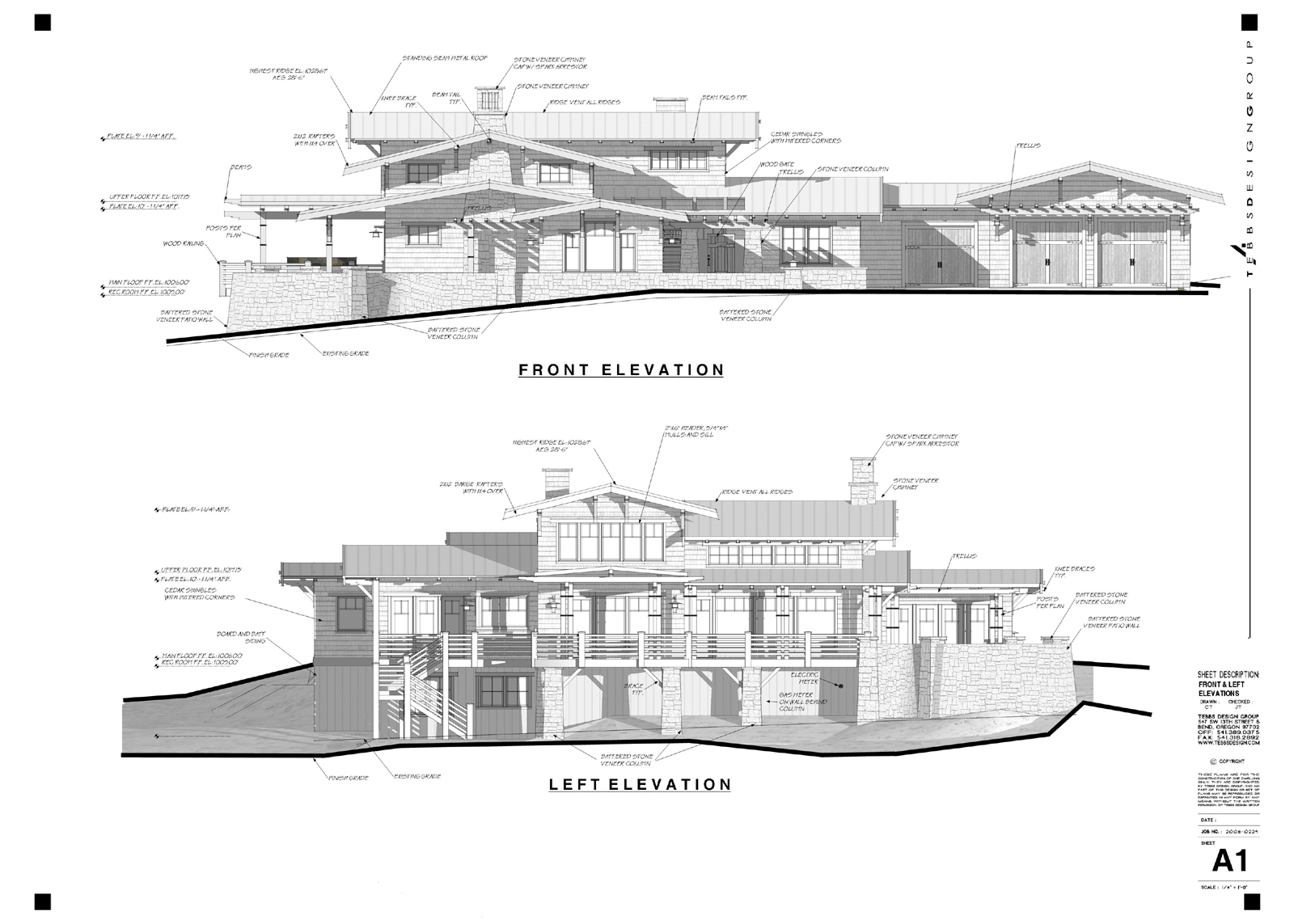
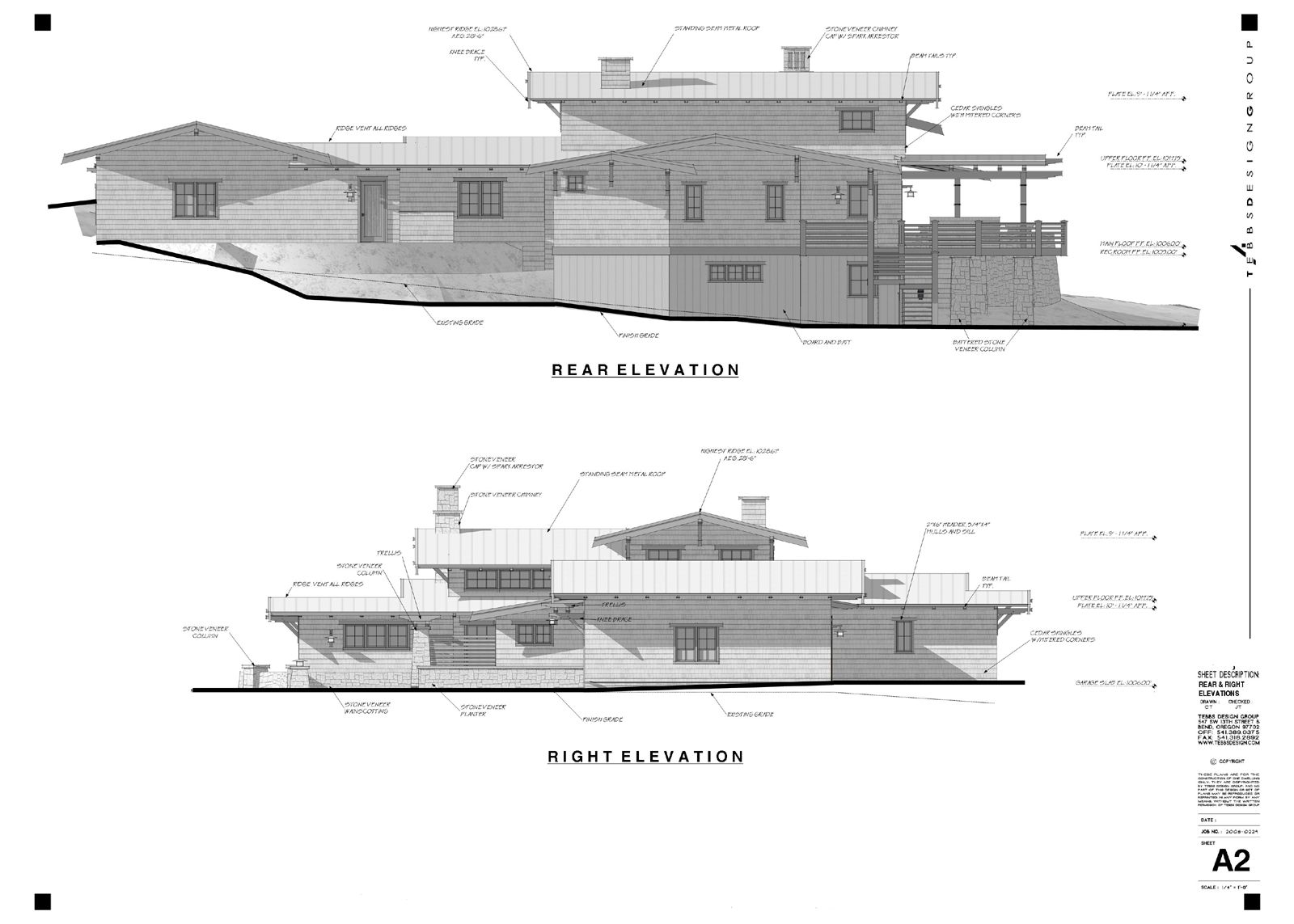
We have been trying to use Layout for printing our elevation drawings, mostly for schematic, and Architectural Review Meetings. I originally tried to use the gray scale ruby, but the values still were coming out to dark when plotting with our Oce' plotter. So I have resorted to changing the material colors, which in reality doesn't take all that long, compared to cleaning up the elevation in DataCAD.
Our work flow method is very similar to what Daniel mentioned earlier in this post, and it sounds like it will be really nice when we upgrade to DataCAD 12. Granted what we have accomplished with layout is far from CD's, but it has been fine for for schematic and Review Board reviews. It is however far from the normal level of detail that we normally apply to our drawings. Any ways I attached a sample that we did just recently for a review. Model created in SU pro7, Border imported as JPG, from DataCAD, post edited in Photoshop to remove clients information, otherwise no other post editing. Applied custom style, that we use with jitter, and extensions on.
-
Dirtsailor, that's very nice work. I like the house, too.
-
Dirtysailor, beautiful design/model; you should post it in the gallery. How did you create the heavy ground line? With the sectioncutface ruby? And why do you have the heavy line in the background, too?
Nice to see another DataCAD user. -
Daniel,
I created the heavy line in Layout, by drawing individual lines, at each angle point I stopped and started a new line. I guess that's the best way, a continuous line produces the mask that will white out areas you want to see. I set the line weight to 5. Another thing I should mention is that we have had issues when keeping section planes in the sketch-up model. If the model is really large we, no matter what settings or styles we use, or scenes, the section cuts will appear in layout.... In this particular model I left a section plane in, so that the building on the uphill side (right Elevation) would be shown, and not just the ground, and this time it seemed to work fine. I have used clipping masks on all of these, elevations to get rid of the stuff we didn't want to see. Its very important that there are no stray lines hiding out in you model, as they really show up once plotted in layout. On another note we have not been able to output to pdf, via the "High" out put mode it does weird things like apply color back into the materials, show section cuts, etc... So these and all our layout sheets are exporting to "medium" out put. I should note that these were set up to print on 30"x42" size paper prior to me turning them into jpg.

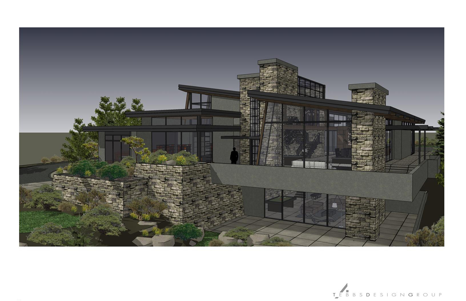
One of our color renders for a different job, just for the heck of it:
Set up in layout for printing on 11x17
Advertisement


