DUUUDE! Exactly what I was talking about!
Here's a few tests:
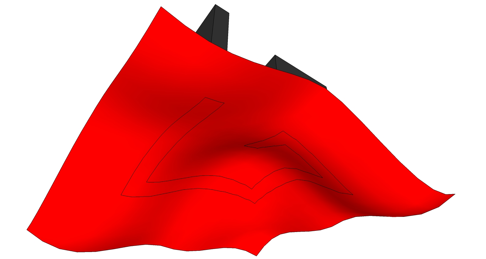
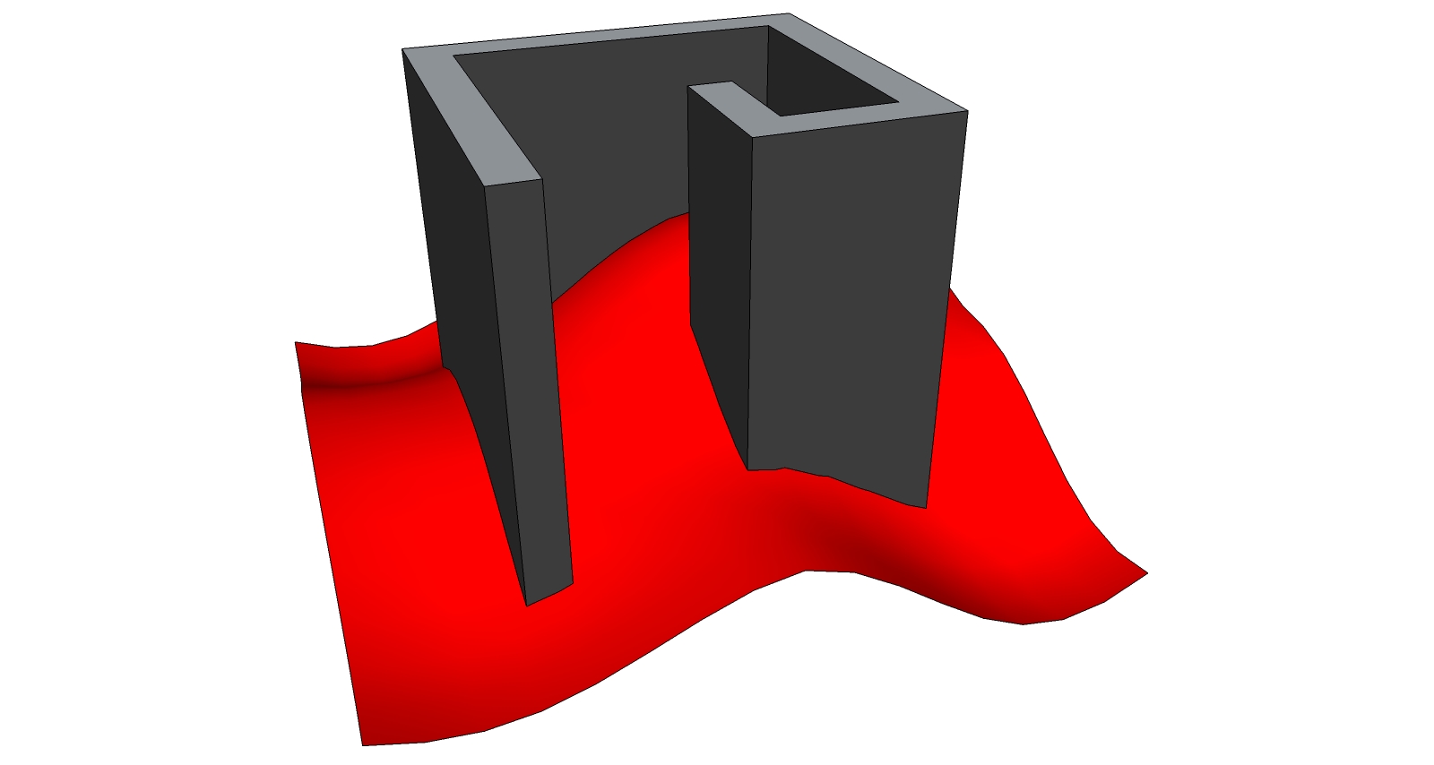
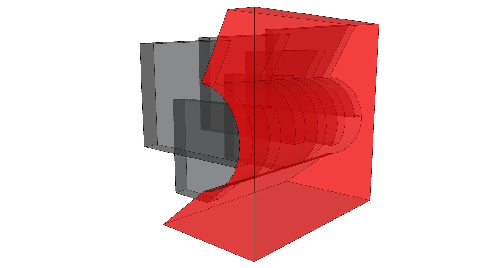
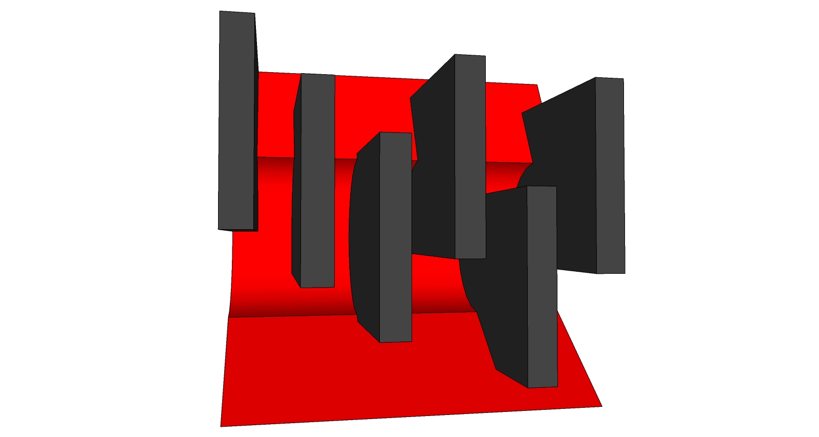
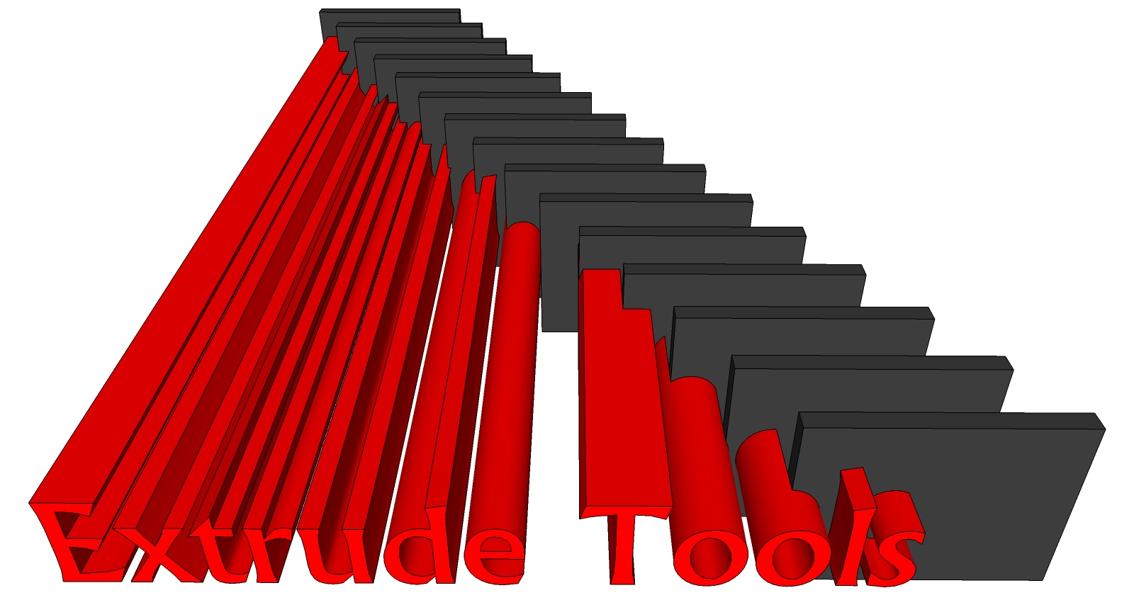
I have a couple more tiny requests to ask, but now i don't have time! 
DUUUDE! Exactly what I was talking about!
Here's a few tests:


I have a couple more tiny requests to ask, but now i don't have time! 
Exactly TIG, performing an automatic extrusion-intersection-deletion would be a possible way, it's complicated though. In both cases being able to automatically add the necessary edges to fit the "shaping" object would make this a killer plugin! thanks for your past and future efforts!
Awesome toolset man, just one thing, I played around with it a little, and I stopped at this point.
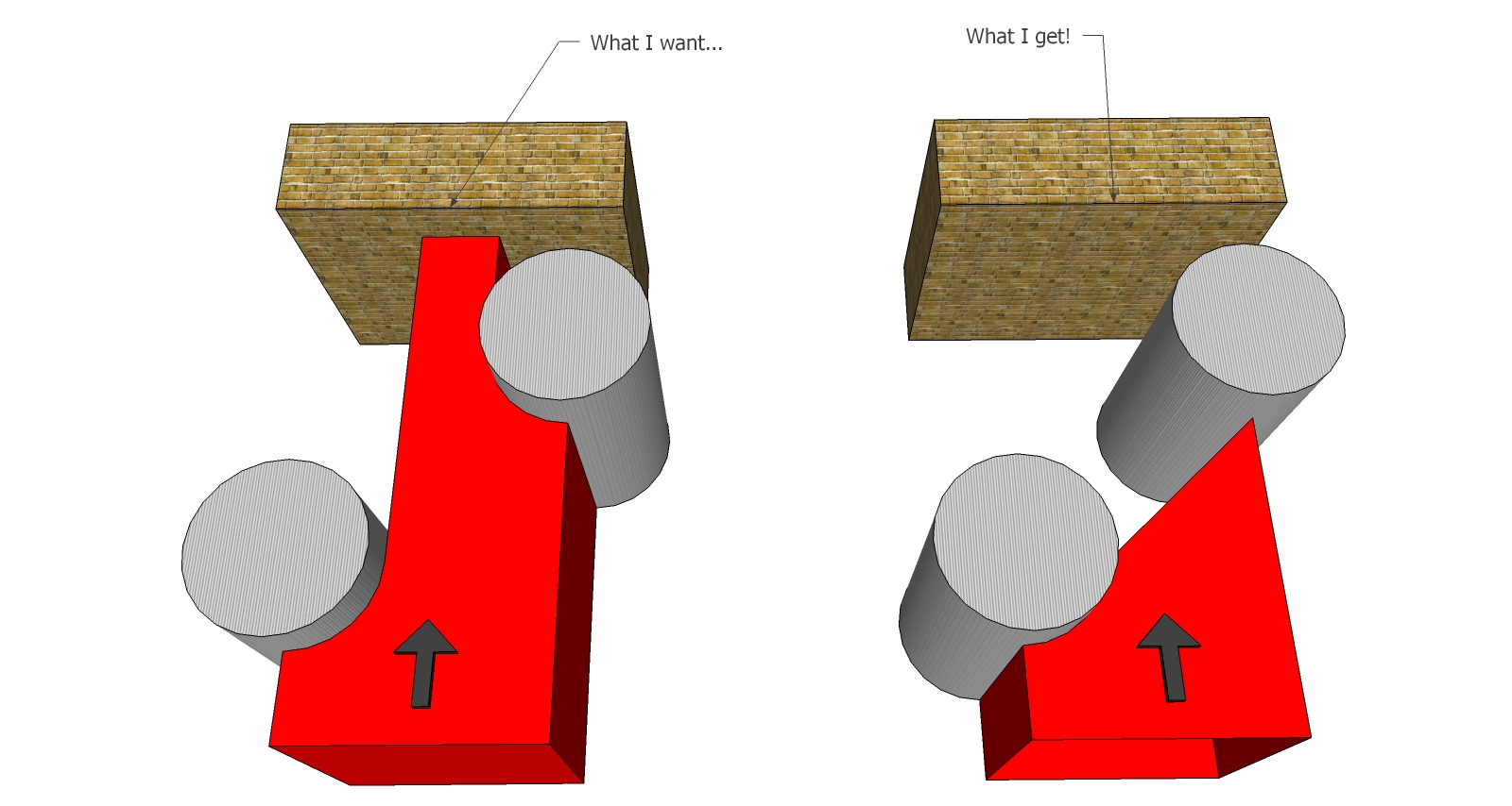
Wouldn't it be great if you could extrude any profile by a vector to any multiple objects, and of course the resulting shape is modeled by the objects it is intersecting with? Is this asking too much?
TIG, I know this might sound silly  , but what's the difference between curviloft and the extrude tools? For what I know they're pretty similar aren't they? can you (or anyone else) point out some cases where is best to use one insted of the other? thanks
Sorry for being ridiculously late in my reply, I've been busy working.
I finally tested your update Fredo, and it works perfectly smooth, and it breezed through the exam!
I can't express how gratefull I am! thank you very much! Hope I wont bother anyone with some crazy request for a while!
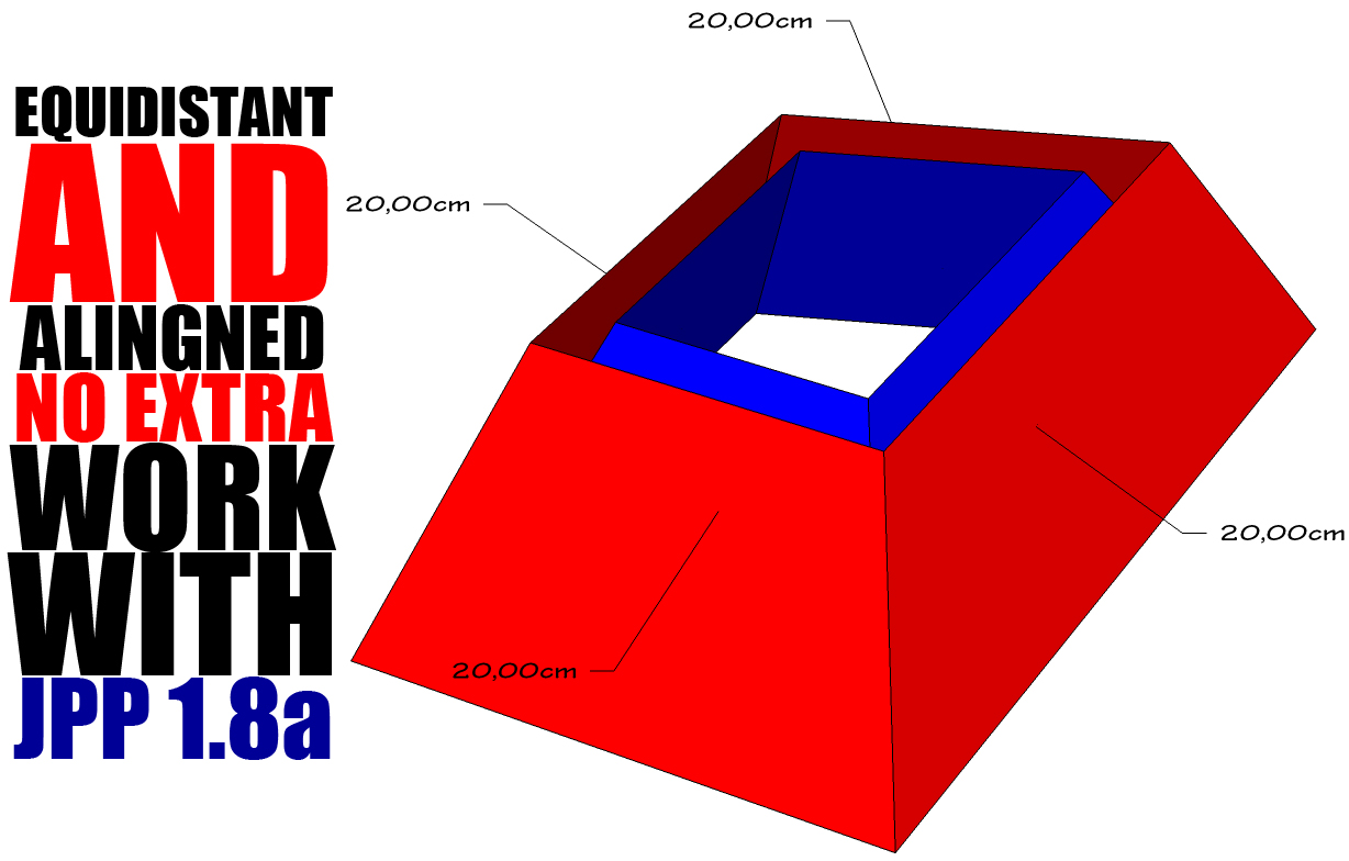
@gilles: DUDEEEEEEEEEE!! I say Bingo! it definately does work! how come I haven't noticed this plugin i don't know!
The funny thing is that in the 1001 pro bit tool bar which I have, there's a tool that behaves just like smartpushpull but can't handle small values, infact it wasn't working in this case.
It would be cool to just be able to interanct with the adjacent faces as well.
I know, I tried to mesure it! what shook me is that the top and bottom are equidistant while the orthogonal faces are not! And as far as i know this is geometrically impossible if the 2 faces are parallel (equidistant). The only solution to this would be that the inset face is not flat, or rather, made by non-coplanar triangles or quad-faces(but that's not the case). Does that even makes sense?
See what you can do! thank you.
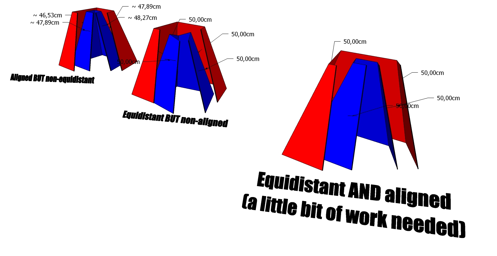
Dude...I don't want to bother more than I've done but  , I tried this method and it actually does work, the top and bottom are now aligned, the thing is now the faces are not equally insetting anymore
  . Seems like that one excludes the other, as shown below:
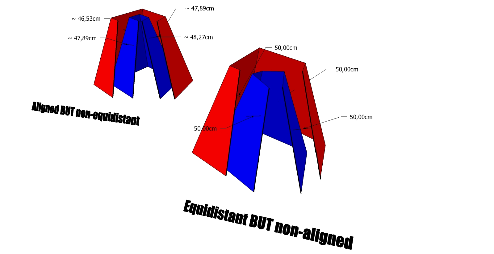
Most likely I am not doing it in the right way, in that case, would you be so kind to explain? Thanks
Thank you fredo for taking care of this! I've immediately tried JointPushPull 1.7 as soon as I could and here's the result:
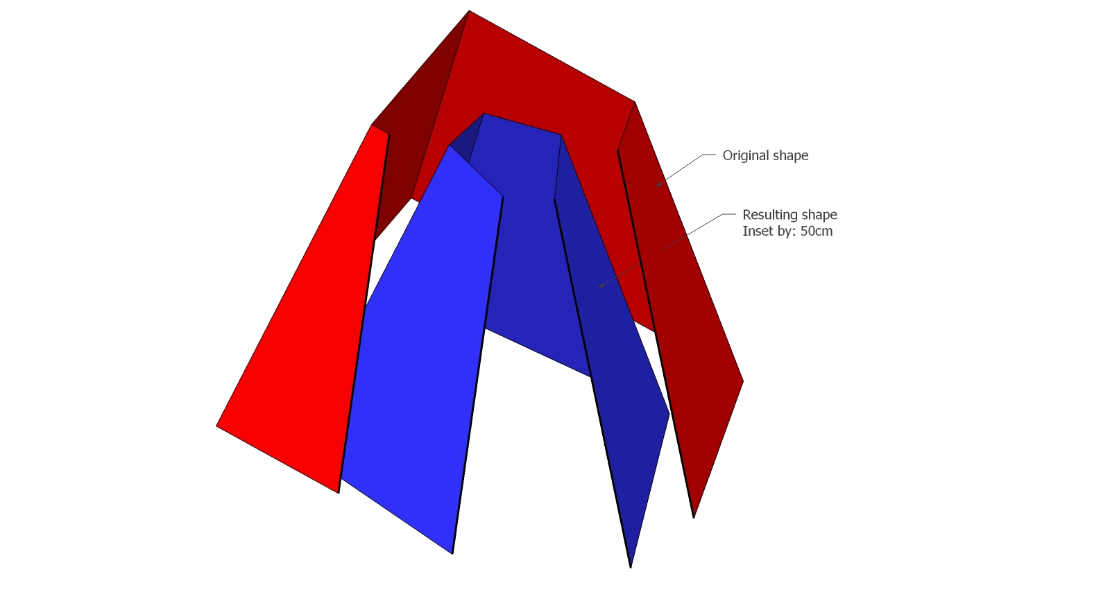
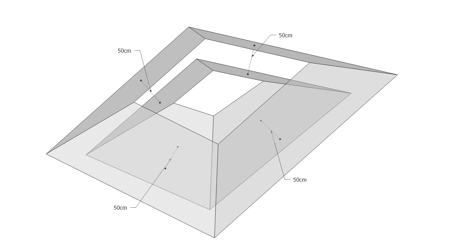
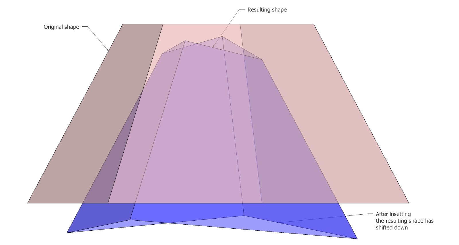
Of course that is not a big deal, it's just about re-shaping the horizontal edges...but since we're here I pointed it out! Let us know if there's a way to fix it!
Great job anyway fredo! Thanks!
Oh...I totaly understand TIG, and thanks in any case for taking the time to try and explain.
Hopefully google is listening and will include this feature natively in the next version.
Anyway in this case I have gotten to the result I was looking for, by using the 2D view to set the crossing points and once the paths were traced I used the procedure shownin the video.
I'll stay tuned in case of news.
<iframe title="YouTube video player" width="1280" height="750" src="http://www.youtube.com/embed/0Qd4z5t0Ns8?rel=0&hd=1" frameborder="0" allowfullscreen></iframe>
@TIG: You wrote on the CADUP description that sketchup can't handle big models like entire buildings with furniture, therefore I don't think is going to be of any use in my case. In any case I'll keep an eye on it for when you'll be done developing it.
thanks!
Alright, thanks TIG I'll try it out! By the way in the meantime I came up with, I believe, the perfect way to export 3D into 2D CAD drawings maintaining geometry separated into layers without flattening or anything (that's why I was trying to use this plug before) just by using colors. In case someone is interested I can make a tutorial off of it.
Hi, I was trying to find a good and painless way to export from skp to autocad to add 2D details, maintaining groups/components and layers while exporting and I came across this usefull plugin. The problem is that it works only with edges ignoring the faces and this makes it unusable in the 3D-->2D workflow because it projects even the edges behind faces as shown in the images.
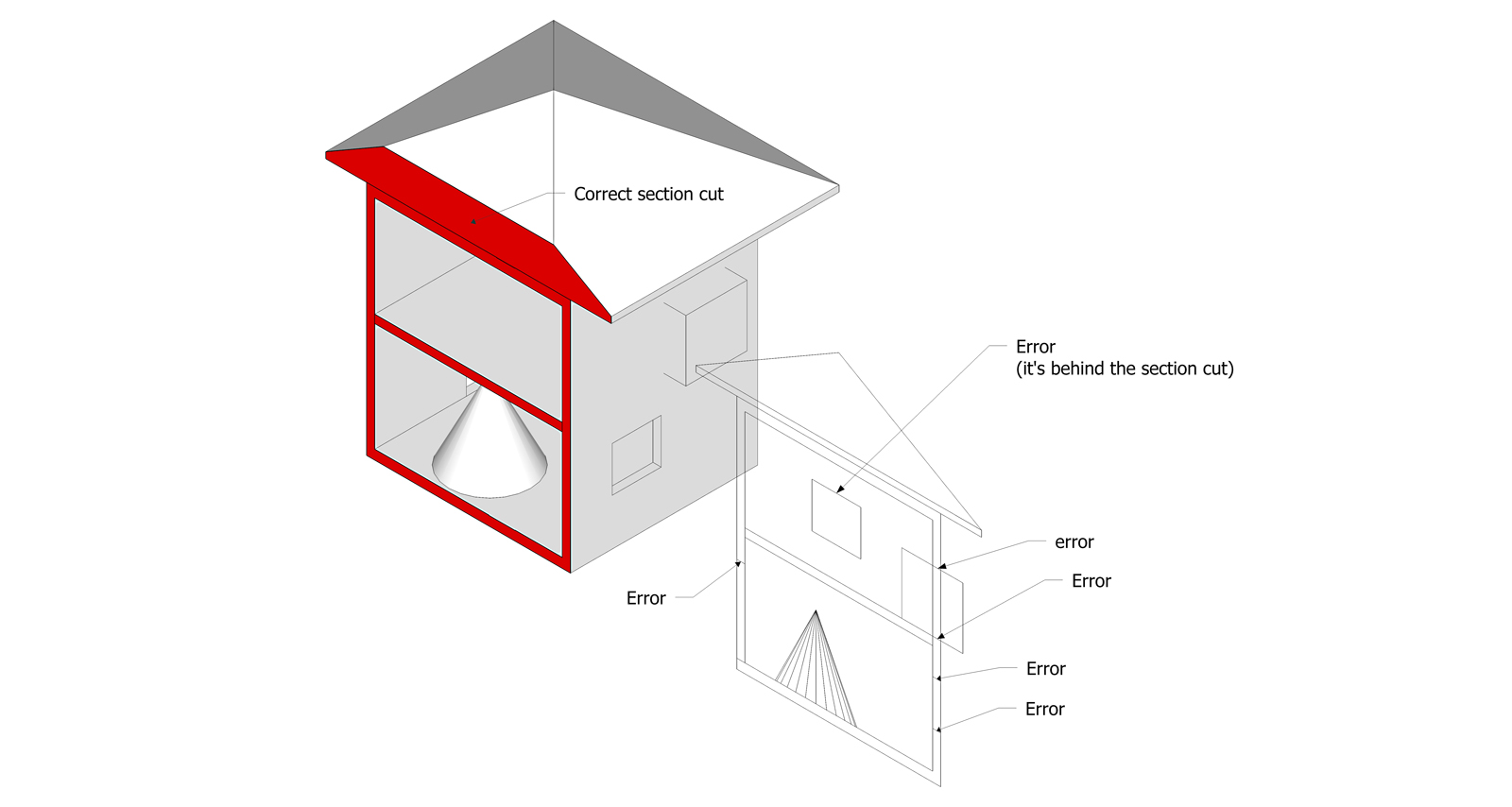
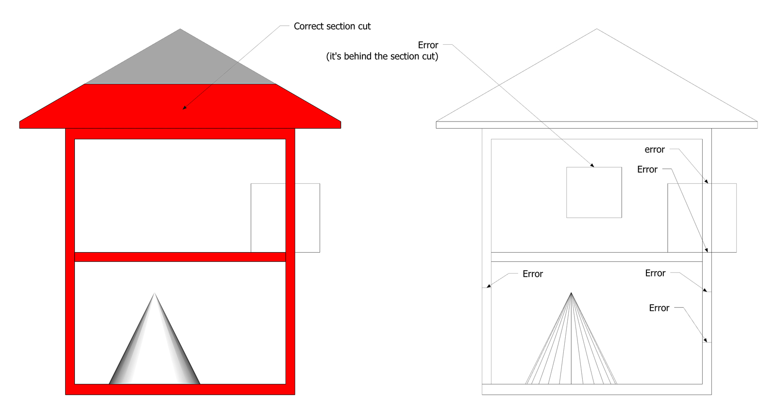
TIG do you think there's any workaround for this? I'd be thankful for the rest of my life 
Awesome! thanks dude, can't wait!
well...I guess I'm gonna have to try a different approach to get the job done...I'll work on that the next days, I'll post the results.
If anyone else is listening and knows a possible suitable solution is welcome to share.
Exactly TIG! so what do you think? is it just a bug or what? How unlucky am I? 
Sorry guys I've been out of town for a while.
Thanks a lot for your precious suggestions (special shout out to TIG).
I tried your workflow, TIG, unfortunately there's something wrong either with the plug (shell) or with me 
I followed step by step, but it's giving unexpected results:
Althoug it's scaling proportionally, which is great, unfortunately it's not insetting by the same distance all the faces, giving weird results: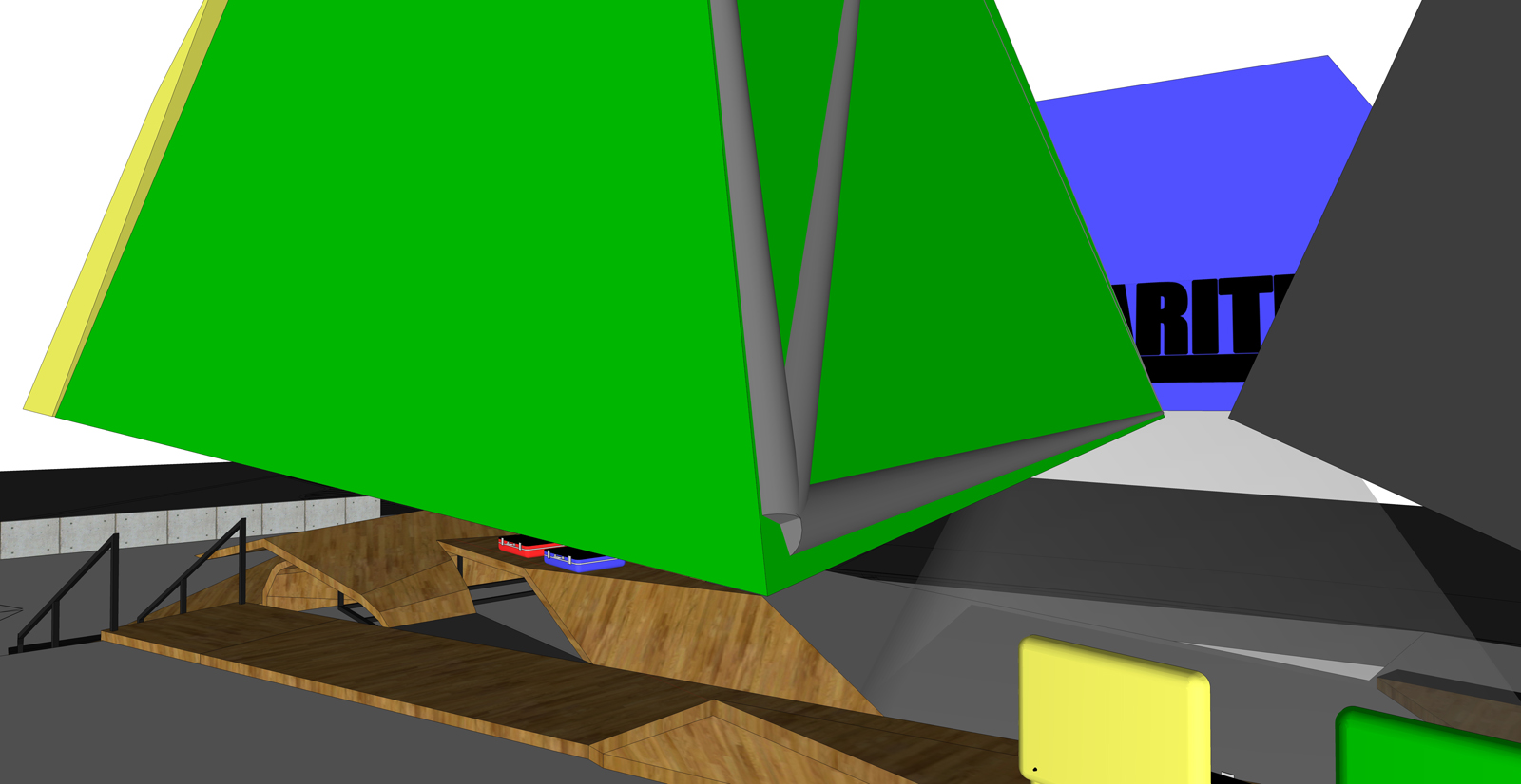
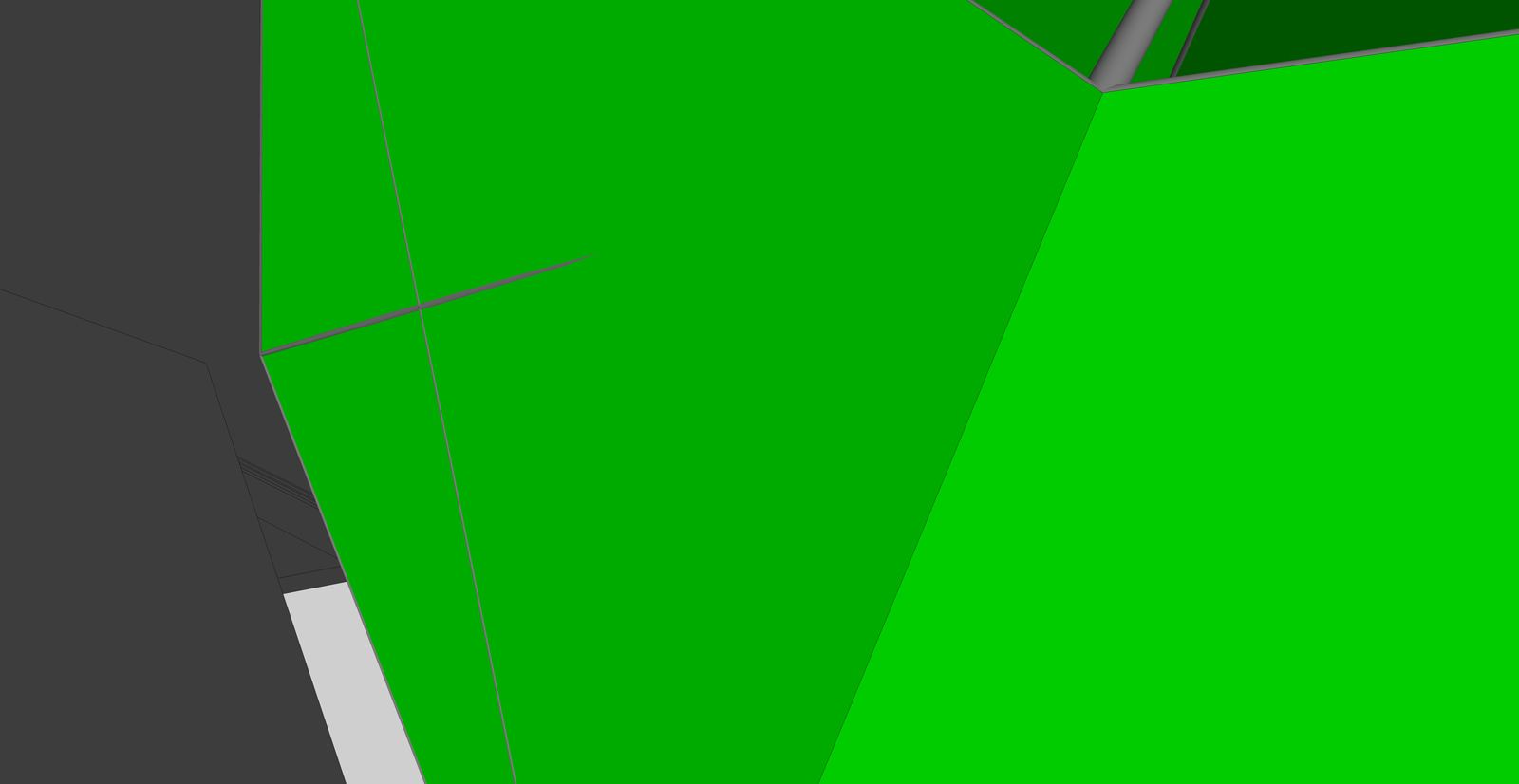
Like I say in the video Rich, for compositive reasons I first modeled the "lampshade shapes";) and now I need to model the structure underneath. Turns out that the only linework that I have available is the one I posted, the same that I can't scale to fit in any way possible 
The next attempt I'll try will be to draw in 2d a couple of sections and a top view and then start from there. I'll post the results!