Well done. I looked at the "map with Isocontours TEXT.dxf" and now all fine!
The other imported dxf files are unchanged good.
Looking forward to see how the word wrapping works.
Oops, your profile's looking a bit empty! To help us tailor your experience, please fill in key details like your SketchUp version, skill level, operating system, and more. Update and save your info on your profile page today!
Urasik Extensions | Lots of new extensions to check out Learn More
Posts
-
RE: [Plugin] importDXFtext
-
RE: [Plugin] importDXFtext
I think I found the issue regarding TEXT:
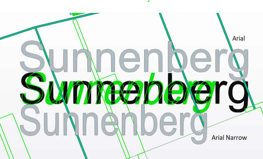
in v4.5 you take the font Arial Narrow, as indicated int he DXF "map with Isocontours TEXT.dxf".
In v4.6 you take the font Arial.
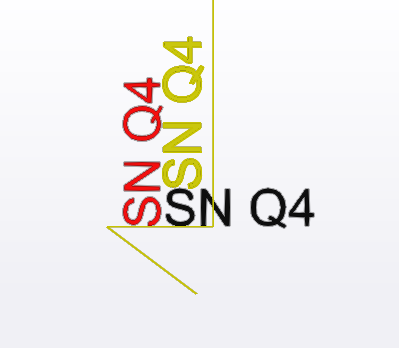
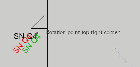
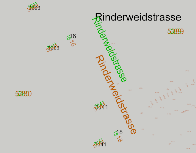
The screen shot below shows in green the original DXF, in black the text imported with v4.6
The text in grey above is a 3DText I created with font Arial. The text in grey at the bopttom is a 3DText I created with font Arial Narrow (same as when imported with v4.5.
Can you change that back for TEXT to how it worked in v4.5?
Oblique angle: Where we will always have a difference is the oblique angle. It is in this DXF 15° - see green text above. As there is no corresponding feature in SketchUp 3DText and the scale tool cannot be used, an approximation would be making the text italic. However italic has an obliquity angle of only 9°.
MTEXT in "map with Isocoutours.dxf" imported with v4.6:
This looks now perfect!MTEXTs and ATEXT in "dxf issues with special chars.dxf" imported with v4.6:
also here all looks very good. Great.
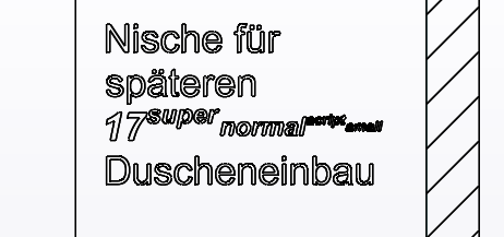
The "Nische für späteren Duscheneinbau is now as well shifted to the right height.
Also the text with "Masse am Bau:"text word wrap: Indeed, the next step would be to do the text word wrap. I have written down a few ideas. From a simple approximation to a luxury implementation.
Unfortunately I forgot to take the notes with me. So I can only send it next week.
But I remember the simple approach
- Get the width of the box (BoxWidth) from code 41 not being empty/missing and not 0
- calculate an average character width (CharWidth). This is done by taking 2/3 of the letter height - which we know from the DXF.
- calculate the number of characters fitting into the width of the box:
NoOfChars = BoxWidth / CharWidth - Loop over each line in the MText (= \P delimited string) and wrap this line using some regexp or below piece of ruby:
BoxWidth= 660
CharHeight = 100
CharWidth = CharHeight * 2/3
NoOfChars = BoxWidth / CharWidth
result = ""
word_array = 'To be or not to be-that is longwordwise the question'.split(/\s/)
line = word_array.shift
word_array.each do |word|
  if (line + " " + word).length <= max_length
    line << " " + word
  elsif word.length > max_length
    result << line + "\n" unless line.empty?
    line = word
  else
    result << line + "\n"
    line = word
  end
end
result << line
puts result
Maybe you can already do something with it and maybe it is even enough.
-
RE: [Plugin] importDXFtext
Sorry, took a bit longer this time.
I dislocated for the weekend and have to install version 4.5 and 4.6 on another PC.
Somehow I have the impression that v4.5 is perfect for TEXT, but 4.6 not anymore.
But let me test all files in details and come back. -
RE: [Plugin] importDXFtext
The first test with the imported file "map with Isocontours TEXT.dxf" showed no differences to the dxf file anymore. Very nice!
Also the file "dxf issues with special chars.dxf" did not show position diffs due to rotation. But there is another issue, which I will report in a later post, as it does not have to do with rotation.
However I have another file called "map with Isocontours.dxf" where all text are MTEXTs. (see attachment)
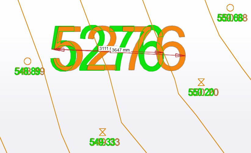
99% are at the right position, but the imported text is slightly wider than the text in dxf.
I checked the dxf and saw, that these MTEXTs have a "width factor" of 0.84 defined. This factor pretty much explains the difference. It is defined on style level. The style is called "ERSTELLTER_STIL_1" and in code 41 you find the 0.84. I think the factor could be applied as well in SketchUp by using the "Scale feature".
Text scaling issue:
During import, this style is also read and the factor properly reported as WidthFactor, but it is not applied.
The console output is:2 DXF STYLES; Name = ERSTELLTER_STIL_1 Height = 0.0 WidthFactor = 0.84 Oblique = 0.0 Flipped = 0 FontFile = FontName = Arial Color = 256In below screen shot, green is the DXF file, red the imported 3DText.
Only two MTEXTS are not right positioned:
It seems it has to do with the letters qpgjy, but this time it is shifted downwards.In below screen shots, green is the DXF file, red the imported 3DText.

-
RE: [Plugin] importDXFtext
I tested v4.4 with the testfile "dxf issues with special chars.dxf".
The displacement of rotated MTexts is the same as with v4.2 reported in this post:http://sketchucation.com/forums/viewtopic.php?f=323&t=23002&p=678093#p678060
-
RE: [Plugin] importDXFtext
TEXT is now all fine. Perfect!
In the same file there are as well some MTEXTs. (The blueish texts).
These MTEXTS are still shifted as soon as there is a rotation involved.
Later I will also send a report based on our other test file.
-
RE: [Plugin] importDXFtext
Makes sense. Then it could be fixed consistently as done with MTEXT.
-
RE: [Plugin] importDXFtext
@tig said:
I got to the bottom of this !
It did process all of the TEXT but then it wasn't adding the 3d-text geometry !!
Now it's fixed...I tested v4.3 re TEXT: IT IS BACK
Great!
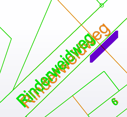
And the position and rotation of TEXT is very precise.
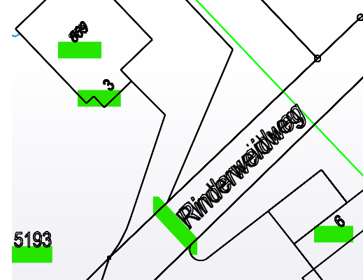
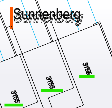
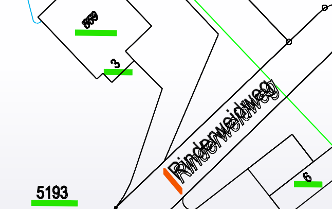
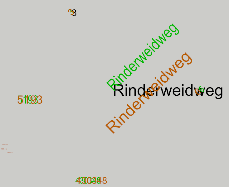
Funny, that two TEXTs ("Sunnenberg" and "Rinderweidweg") are slightly off (only by a 1/4 of the font height).
In below screen shots, green are TEXTs that are precisely positioned, red marked the two longer TEXTs that are a bit shifted. I think it can be ignored, but still wanted to let you know.
-
RE: [Plugin] importDXFtext
I tested v4.2: better again
TEXTs are still not imported, the console output is a bit different now, but in Sketchup there are no TEXT groups created. Only 25 MTEXT and 225 ATEXT groups.
I am testing btw with SketchUp 2022. DXFImport v3.4 is running on SketchUp 2021.
console output of importing "map with Isocontours TEXT.dxf":
Making 74 TEXT Entities...
74 : 0
Making 25 MTEXT Entities...
25 : 0
Making 436 ATTRIBUTE TEXT Entities...
225 : 211Rotation testing (dxf issues with special chars.dxf):
Here the 3DText objects that were far off in the lat version, are now closer again, but still not fully correct:
It seems the attachment point for rotation is not read correctly:In below screen shots, black is the unrotated text from v3.4, green is where it should be according to the DXF definition, red is where the import is placed.
Looks like all are attachment point issues, except the "Masse am Bau:" which is shifted down since version 3.4.
-
RE: [Plugin] importDXFtext
Yes, it is the file called map with Isocontours TEXT.dxf.
I am running with v4.1
after the import finished, I see only 250 sub groups. 225 ATEXT and 25 MTEXT.
They are either called "ATEXT #..." or "MTEXT #...".
But there are no sub groups called "TEXT #..." in the outliner.The first TEXT entry listed in the console is:
Layer = 01139
Color = 0
X = 2677161.876174174
Y = 1237562.802
Z = 0.0
Height = 0.9999999999999997
Text = 430287
Oblique = 15.0
Justification_H = 2
Justification_V = 2
Style = STANDARD
Rotation = 0.0Yes, the origin is far off. This is the Swiss coordinate system LV95.
There are or instance two TEXT called Rinderweidstrasse and Rinderweidweg. These should be easily visible in Sketchup in the very top right of he imported group, but they do not exist.
(choose parallel projection, top view, then in the outliner select an ATEXT and then "yoom selection" in the context menu)
BTW, the first 12 MTEXT are in the bottom left corner of the group near the Origin, the other MTEXTs and the ATEXTs are in the top right corner of the group. -
RE: [Plugin] importDXFtext
Thanks. Can you also look into why TEXTs are not created anymore in SketchUp, even though in the console it says that "Making .. TEXT Entities"
? -
RE: [Plugin] importDXFtext
The "Knickarmmarkise" is now good and yes, the attachment point is 6, not 5.
But all other MTEXTs are now either a bit off or completely off.
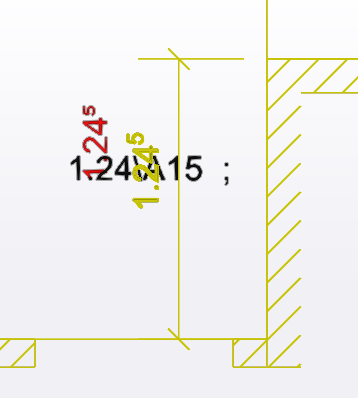
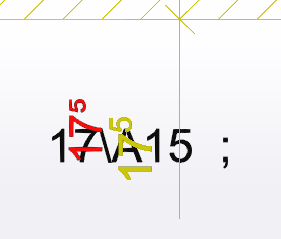
It looks like that the higher the rotation angle the more off the text is placed.
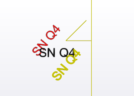
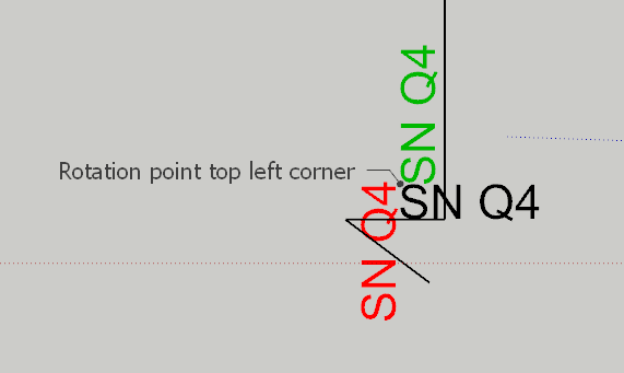
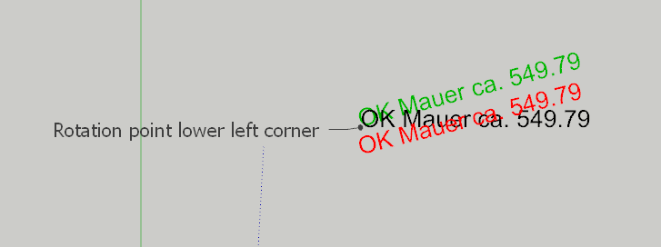
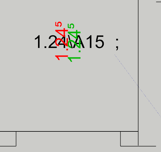
The "SN Q4" texts are about 26meter off, the dimension value 17^5 is 23m off, the 1.24^5 dimension value is 34meter off. the "OK Mauer ca. 549.79" is about 6m off to the right.The "Masse am Bau:" has not changed position compared to version 4.0.
BTW in version 3.4, 3.5, 3.6, etc it was correct. Can you not compare to the code of v3.4? -
RE: [Plugin] importDXFtext
Much better. Thanks.
in the test file "dxf issues with special chars.dxf" there are now only two issues left.
The text "Knickarmmarkise" has the attachment point in the "middle center", but I think you take the point "left center". Therefore the text is shifted to the right. Can you implement the attachment point "middle center" / "right center"?
In below screen shot, green is the position where it should be, red the position produced by version v4.0

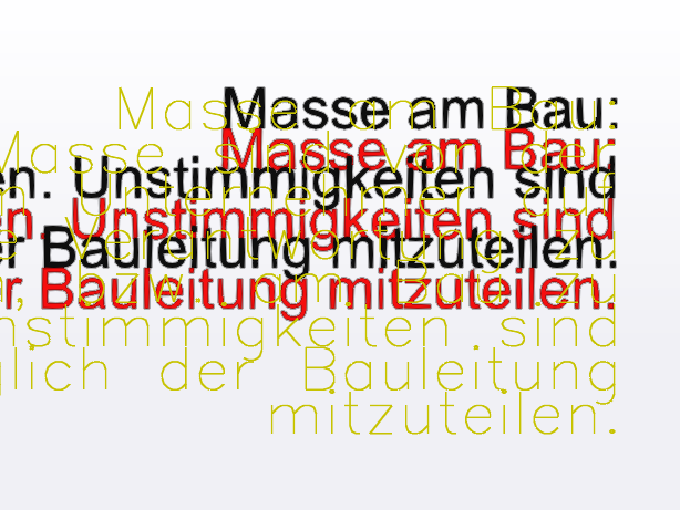
The large text starting with "Masse am Bau:" is nicely aligned left, but it is shifted downwards by exactly one letter height. In version 3.4 (to which I compare version 4.0) this was correctly placed.
In below screen shot, green is the (correct) position from version 3.4, red the position produced by version 4.0.

P.S. TEXT entities still not working properly:
version 4.0, says in the console, it is doing TEXT, but they are not created in SketchUp!
I get :
...
74 TEXT ENTITIES:
...
Making 74 TEXT Entities...
Making 25 MTEXT Entities...
Making 436 ATTRIBUTE TEXT Entities...
...BUT: the TEXT entities are NOT CREATED in SketchUp.
-
RE: [Plugin] importDXFtext
@tig said:
The -ve sign should move up ??
Weissputz has a downstanding 'p' again they should push up ??
I'll investigate...Yes, it worked in version 3.6. All nicely shifted up. Including characters like °'`^". They were shifted up to the top.
-
RE: [Plugin] importDXFtext
No problem. Shit happens ,-) and for this I test
Another issue came now back.
The shift of the 3D-Text in case there are letters going beyond the writing base line:

The type of text is helpful. Could you also add the content of the text somewhere?
Then I could even search for a specific 3DText. It does not have to be the full text. Maybe the first 20 chars, so that the outliner does not yet get a horizontal scroll bar?

-
RE: [Plugin] importDXFtext
Whow, that was quick. I tested.
The TEXT is back, but the Block Attribute Text is now gone

For the file "dxf issues with special chars.dxf"
with version 3.4:8 STYLES:
16 LAYERS:
0 TEXT ENTITIES:
11 MTEXT ENTITIES:
16 ATTRIBUTE TEXT ENTITIES:
...
Making 0 TEXT Entities...
Making 11 MTEXT Entities...
Making 16 ATTRIBUTE TEXT Entities...with version 3.8:
8 DXF STYLES:
16 DXF LAYERS:
0 TEXT ENTITIES:
11 MTEXT ENTITIES:
16 ATTRIBUTE TEXT ENTITIES:
...
Making 0 TEXT Entities...
Making 11 MTEXT Entities...
...For the file "map with Isocontours TEXT.dxf"
with version 3.4:
4 STYLES:
67 LAYERS:
74 TEXT ENTITIES:
25 MTEXT ENTITIES:
436 ATTRIBUTE TEXT ENTITIES:
...
Making 74 TEXT Entities...
Making 25 MTEXT Entities...
Making 436 ATTRIBUTE TEXT Entities...with version 3.8:
4 DXF STYLES:
67 DXF LAYERS:
74 TEXT ENTITIES:
25 MTEXT ENTITIES:
436 ATTRIBUTE TEXT ENTITIES:
...
Making 74 TEXT Entities...
Making 25 MTEXT Entities...
... -
RE: [Plugin] importDXFtext
@tig said:
Thanks for the feedback.
Perhaps I need to locate it first, then rotate about that point...
I'll investigate... code-71Yes, angles are

I think so too, as 3D text cannot be created indicating the position. So the attachment point can be picked from the bounding box only in a second step. And then the attachment point is moved to the position indicated in the codes (10,20,30) and the rotation (around the attachment point) applied as indicated in codes (11,21,31) or code 50. -
RE: [Plugin] importDXFtext
Since version 3.5 and higher another issue has sneaked in: TEXT objects are not imported anymore
(our main test file does not have text objects, so I did not realize it before)
There should be 74 TEXT ENTITIES imported from the attached file called
"map with Isocontours TEXT.dxf"
Currently the console output looks like this:-------------------------------------------- importDXFtext -------------------------------------------- DXF = 'D;\xxx\Sketchup\Import\dwgtest\map with Isocontours TEXT.dxf' UNITS = 'm' 4 STYLES; .... 67 LAYERS; .... 0 TEXT ENTITIES; 25 MTEXT ENTITIES; .... 436 ATTRIBUTE TEXT ENTITIES; ....Rotation
MText Rotation angle looks good. But the position is not right anymore. I assume the issue is that the wrong rotation (attachment) point is taken.
What I found in the ACAD documentation on MTEXT:@unknownuser said:
MTEXT code 71: Attachment point:
Values mean: 1 = Top left; 2 = Top center; 3 = Top right
4 = Middle left; 5 = Middle center; 6 = Middle right
7 = Bottom left; 8 = Bottom center; 9 = Bottom rightWhat I found in the ACAD documentation on rotation angles and text points in relation to text justification:
MTEXT codes 10, 20, 30; x,y,z coord for Insertion point
MTEXT code 50; Rotation angle in radians
MTEXT codes 11,21,31; x, y, z coord of X-axis direction vector (in WCS)
                      A group code 50 (rotation angle in radians) passed as DXF input is converted
                      to the equivalent direction vector ([u]if both a code 50 and codes 11, 21, 31
                      are passed, the last one wins)[/u]. This is provided as a convenience for
                      conversions from text objects
MTEXT code 71; Attachment point;
               Values are; 1 = Top left; 2 = Top center; 3 = Top right
                           4 = Middle left; 5 = Middle center; 6 = Middle right
                           7 = Bottom left; 8 = Bottom center; 9 = Bottom right

TEXT codes 10, 20, 30; x, y, z coord for First alignment point (in OCS)
TEXT code 50; Text rotation (optional; default = 0)
TEXT codes 11,21,31; x, y, z coord for Second alignment point (in OCS) (optional)
                     These values are meaningful only if the value of a 72 or 73 group is nonzero
                     (if the justification is anything other than baseline/left)
TEXT code 72; Horizontal text justification type (optional, default = 0) integer codes
              (not bit-coded)
              values are; 0 = Left; 1= Center; 2 = Right
                          3 = Aligned (if vertical alignment = 0)
                          4 = Middle (if vertical alignment = 0)
                          5 = Fit (if vertical alignment = 0)
              See the Group 72 and 73 integer codes table for clarification
TEXT code 73; Vertical text justification type (optional, default = 0); integer codes
              (not bit-coded);
              values are; 0 = Baseline; 1 = Bottom; 2 = Middle; 3 = Top
              See the Group 72 and 73 integer codes table for clarification

A-TEXT codes 10, 20, 30; x,y,z coord for Text start point (in OCS)
A-TEXT code 50; Text rotation (optional; default = 0)
A-TEXT codes 11,21,31; x, y, z coord for Alignment point (in OCS) (optional)
                       Present only if 72 or 74 group is present and nonzero
A-TEXT code 72; Horizontal text justification type (optional; default = 0). See TEXT group codes
A-TEXT code 74; Vertical text justification type (optional; default = 0). See group code 73 in TEXT
Examples for Rotation issues with MTEXT.
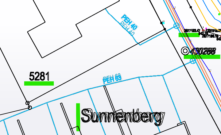
Below cases are based on our dxf test file called "dxf issues with special chars.dxf":
- The black text is the unrotated text produced from v3.4
- The red text is the rotated text from v3.7
- The green text is as it should be (taken from trimble viewer) using the indicated rotation point
Good examples are also in the file "map with Isocontours.dxf", for instance the texts "Rinderweidstrasse" and "Rindwerweidweg".
Below examples have the same black/green/red colouring.
Most rotated green and red texts to not overlap. Only unrotated and the rotated text "3" match.
As **a further test, **the attached dxf "map with Isocontours TEXT.dxf" can be used. It contains mostly the same text as the previous sent file "map with Isocontours.dxf", just that most MTEXTs are TEXT. So when importing both in SketchUp, texts should be at the same position, except the descriptions of the isocontours, because these are shifted a bit.
-
RE: [Plugin] importDXFtext
@tig said:
The
2.88\A15is therefore equal to2.88⁵
I can trap for that, but are there any other decimal parts e.g. 2.88³ ??I see that \A is a DXF alignment code, where 1 is btm, 2 is center, 3 is top
The part after that is the formatted string - e.g. 5
It also has a trailing ; that needs stripping....I have created an additional test case (see attached dxf file) with the following dxf script:
\A1;Nische für späteren \A1;{\fArial|b1|i1|c0|p34;17\fArial|b1|i1|c0|p34;\A1{\H.66x;\Ssuper;normal}\A1{\H.36x;\Sscript;small}} DuscheneinbauBut I think this is really pushing it.
I think a formatting command starts with a "" and ends with a ";"
- The \H..x; command indicates the text height as a factor.
- The \S...; command is the superscript. The text to superscript starts right after the "S" until the ";".
- The \Ax; command can also be written without the ending ; as it takes only one parameter.
- curled brackets {} are to limit a command to the block inside the curled brackets.
The import looks like this:

It should look like this:
-
RE: [Plugin] importDXFtext
Looks very nice! Thanks.
This numbering format with the "mm" number shown superscripted only shows a whole number, no decimals in the superscript.
But in theory there could be also more than one digit/character superscript.I have attached another dxf which is as received. It contains a map and isocontours with a lot of text. Here you see, that rotating the text along the contours would be very helpful.
The coordinate system is the Swiss coordinate system LV95.
The origin is 2'677'085 m west and 1'237'410 m south of the lower left corner.I have another similar file which is in 3D. But I think the 2D is good to start with.