I would group a lot of those edges/faces into groups
Oops, your profile's looking a bit empty! To help us tailor your experience, please fill in key details like your SketchUp version, skill level, operating system, and more. Update and save your info on your profile page today!
Check out Febhouse | New extensions for Shadow Analysis in SketchUp Download
P
Offline
Posts
-
RE: Increasing Sketchup's Performance?
-
RE: DC formulas change after importing multiple DC's
Hi
sorry, I changed the "e1_back_type" to "back_type" in B2D when I first tried to figure it out. forgot about it when I look at it again before posting
-
RE: DC formulas change after importing multiple DC's
Hi,
I believe the solution is to place all your cupboard units into one drawing. You can right click an offending (red ink) component and click redraw. I believe it should update without trying to reference a copy. you may have to repeat a few times, so all happy with each other
Then right click and save it back to your component folderI did this with the three you posted and got them to be happy with each others existence without changing any attribute references
-
RE: Need Help: DC constrain min/max scaling size
Hi
using the conditional statement is correct,(<5) then smallest (current & 50)
note for metric you have to use 2.54 as a conversion from inches to cm when getting or using the current valueexample attached
Philip
-
RE: DC formulas change after importing multiple DC's
Hi
I believe the solution is to reference the sub-components or groups from xxxx!, wd1! or whatever! to parent!
use the generic term, then parent name does not matterFirst I build a new component by clicking in the formula values then when happy change the references to the parent with the term parent
Philip
-
RE: Dynamic component input format
Hi
One way is to input into a text attribute, then convert the contents using the value and string functions
updated,,,
Attached a component with a calculation group (no size, could set hidden) for lenX,lenY,lenZ
(better labels than last)Philip
-
RE: Is it really worth upgrading from SU 8 Pro to SU 2013 Pro
if you upgrade now it includes the 2014 upgrade (1 year support from date of purchase), if you upgrade later, ..... you may be asked to pay more? does anyone knows?
Philip
-
RE: A problem with negative rotation
common problem fixed by putting the attribute within quote marks, "RotZ"
animate("RotZ",-RotationExample!RotationAngle,0)
the case is same for using Current("LenX")
is like using absolute and relative references in a spreadsheet
I dont know the explaination of this behaviour, only the fix
Philip
-
RE: Help needed with faces
Hi
For complex roof plan,first make a face of the common pitching point (fascia line) then offset a given known distance, then select the inner plane and auto-fold the correct height to make all the hips, valleys, then use the methods outlined above
this is for a roof with all the same pitch
Philip
-
RE: Facing a problem to creatdynamic Wall With Opening at centre
Hi Shaan
some ideas....Suggest that all composite components be made of solid groups, thus can use "outer shell" to make one solid and explode all the contents.
Recommend a component like wrapper to protect axis contents and show attributes you want the report writer to see. The next level down should be a group that drives its sub groups and takes reported data from the wrapper. At this level all attribute changes should be made.
Thus this level can be then "outer shelled and exploded" leaving solid geometry behind. ideal for the report writer.If at a later date you want to change then one can place the original working component within this one after deleting the geometry, explode to expose the inner group then escape back to the model and force a redraw to update the outer component wrapper.
This approach would assure a smaller file, with good reporting on complete shapes rather than a host of little bits
Hidden geometry should be placed where it can be absorbed where possible, or collected at a bin point for deleting
Voids or openings can be created by attaching cutting faces within the component, however they can only work after exploding the outer component, so attribute data need to located with rim maybe set in a lower sub group, so can be reattached later
I notice you are using "parent!" which is required for this type of swapping
cheers
Philip
-
RE: How can I bevel an edge into TWO edges in sketchup?!
Hi
you can select a face, move/copy (M & ctrl)to desired position rather than edge by edge
if you require a internal bevel, then place 3 faces , select center edges and scale to a reference
the beauty of Sketchup is realising the control and simple multiple functions in
using the keypad shortcutslike autofold.... M & alt
-
RE: Round peg square hole?
Hi
One should group objects before adding others , build the base, right click make group, build the cylinder or another object on top, can group this object too if required. Enter either objects and perform push-pull or any other edits as required.When happy and if you want objects to attach and act as one, either explode the groups and make one, or make the groups a group or component
-
RE: Some pain in the as face behavering problems
Hi
extrude the section up and down, intersect with model, clean up, fixed. it can auto-fold
the section must be close to, but not exactly in same plane
Philip
-
RE: Some problems with DC
Hi Vim,
There are some posts covering the metric / imperial "bug" with DCs, "DCs in metric?" for example.
the 2.54 conversionThe parents "onClick" will over rule the children, so multiple "onClick" need to be placed in same level.
Can use multiple statements on the onClick separated by ;
Can use it as a trigger to apply conditional outcomesexample attached
Cheers
Philip
both handles need to be turned to 90 deg , then door moves on click
-
RE: Changing part of a geometry from dc attribute
Hi
With regards ruby it would pay to post your enquiry in the developers' forum to get more responses
Personally I am in a similar position, learning ruby, building DC to be used with code, interest is framing
With regards swapping, and cut list
consider the example again with a group of Right end components
if you copy the side DC and replace the geometry within one of the Right ends with it, set the DC to required parameters, then right click, outer shell then explode, all updated and can be seen as complete in cut listCheers
Philip
-
RE: Changing part of a geometry from dc attribute
Hi Jonathan
If you decide to make the DC using sub groups, then I recommend you make them out of solids so that if you want to 3D print, CAM or BOM, then you can convert to single object using the outer shell command (right click for context menu).
So hide rather than delete shared faces and lines. Where you require an outline use a cubic shape with one or two axis length set to zero and hide other lines where necessary. for multi hidden sub groups that are not part of finish have all their length attributes =0 and position so it will become part of the final shape on either explosion or use of the outer shell command. (sample attribute in form ...X =if(Hidden,0,parent!LenX-LenX)
attached sample
The first side is made of two groups with no hidden geometry, on using the outer shell command they become one, the obvious common lines are deleted.The second is more involved, using 3 solid groups, it likewise can be changed to a single group of geometry using the outer shell. The outline is a solid group with its Z length set to "zero" (very small)
Lots to think about?
Cheers
Philip
-
RE: 4 mitred edges
Hi
for a panel, draw shape them offset the thickness, select the middle area and use move(M) start operation then press "alt" to auto fold, enter thickness done.
Can do for roof pitch also, offset run, move up (alt) the heightCheers
Philip


-
RE: How much would you Pay? To improve SketchUp
What if there was no free version and the whole package was $200.00 (except a free educational version) increasing @ 10 percent per year for R&D?
-
RE: Variable Rabbet and Dado Depth/Width for a Dynamic Component
Hi Vigy,
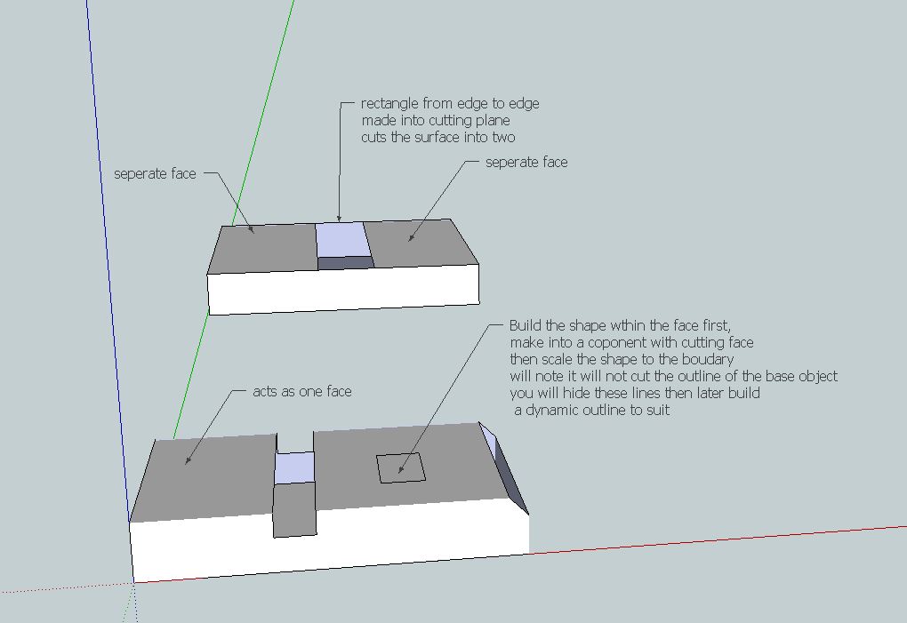
To make the holes, they are first contained within the surface then expanded to the edges, this makes the remaining surface act as one, and "self heals" as per attachment.
Its probably best to build the mitre ends as 3 part component if you wish to use Dynamic Components
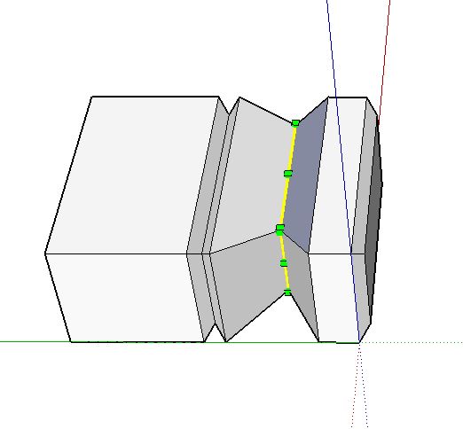
At some point though your efforts may be best spent on the ruby code. Its fairly simple to move an edge to form the mitre using a script.I have considered your concept of engraving, which is to develop the hole further, attached is a reversed moulding to build a cutout in a panel.
The biggest problem with DC's is that they soon become memory hungry and "clunky".
Cheers for now
still experimenting
PhilipPS
after a weekend check the mitre box in wood working forum for update