did I not put 3ds in there sorry... I thought I put all 3 extensions in there...
thanks Mateo, for the catch...
did I not put 3ds in there sorry... I thought I put all 3 extensions in there...
thanks Mateo, for the catch...
you need to export into a .dwg format or a .obj
these will both go into max...
you'll have layering and material issues... like not having any at all...
thank you Howard...
Curved Walls Using Flex-C and RickW’s "copy along a path" ruby
I'm here to help some of you designers with curved walls...
we will be using components made from a product called Flex-C track you can find out more about the product here... http://www.flexc.com/
we’ll also be using a ruby script provided by RickW can learn more about the script here http://forum.sketchup.com/showthread.php?t=41083
now that you have read about the script you can download the script and my Flex-C components here at my website...
http://www.aboveallhouseplans.com/Flex-C.zip
install them to your component directory with your other framing units...
Now you’re ready to start.
Step 1. insert one Flex-C unit into your model,
Step 2. draw an Arc a Curve or Bezier curve
Step 3. use the “copy along a path” tool, from the drop down menu under Plug-ins to set the Flex-C unit along the curve... (be sure to type in the length of the component from “hole to hole” for the spacing between the units along the path either 3-1/2" or 5-1/2" depending on if it's an interior wall or exterior.
Shazamm… you may have a few doubled up components or slightly offset extra units, but just delete them. now this isn't perfect but it goes along way in helping to building framing drawings for curved walls... you'll either need to edit the components after they are curved to delete some of the 2x4's but I'm sure it's less work than before...
so there you are and happy Curving....
sweet... thank you sir.
yeah I never have reason to use that always face camera deal... what do you use it for?
Personally, I have a second sketchup window open, to make new components... this helps with centering, and then I make my model using the center of the axis
awesome Boo... thanks for this.
I run into this issue all the time with windows and doors in walls.
oh of course not... there is more than one way to skin a ______...
DzineTech,
yes you are correct in your assumption, however if you were to cut a section above the window, most people have removed those faces, and thus the window only shows up if you cut the section directly through the area in which the window is located.
so we may both be right...
DzineTech points out that it is the proper way to model, to remove any faces which are not seen or used. which I agree with.
and as he or she points out, you can model the house and make construction docs from it using his method, if the all the windows and openings are at the same level, through out the home. however if some windows or openings are above others with in the same floor or plane, then you will not see them when you do a section cut at the nominal level.
am I being clear? I'm trying, I'll make some screenshots later like DzineTech suggested. and I'll try to get part three done.
yes I need to buckle down and get part 3 done... the home is complete...
here are some screenshots
there are a few problems with it, but I never really complete anything... I'm always off to the next project
there is a method to my madness...
the reason I want those extra faces... it prepare for autocad and drafting a house's construction documents. if this were just a 3D model I would agree... but it's for a pro to make a real house out of.... so we need to be able to cut sections at any poin where a window is and see the mullions...
thanks for you advice though.
@unknownuser said:
The tutorial is very good - I'm just a beginner.
Wondering where we find Part 1?
here ya go...
thanks Shaun for posting the link... my lil SU Groupie... 
emahfuz, yes Passion... is the name, I knew being Brazilian you would notice...
thedifferenz,
how your structure will look in the real world, to be as real as possible... use real world materials. and I mean componenets really. if you are going to build a wall, don't just draw a face and pull it up, create 2x4's 2x6's 4'x8' plywood and sheet rock, and then manipulate those comonents over and over, using the "make unique" command on the context menu. put these together to create your wall and then you will know exactly what the framer in the field will run up against.
"But, I am not confident about using sketchup to do the elevation of my house. Because, i learned sketchup using trial-and-error method, which is time consuming. And i lack the basics of drawings. I always used to get confused about where my line is getting drawn, is it in x axis/yaxis/z axis... and i still dont know how to draw a line is a particular axis... i click here, i click there, then draw and will check where it came up, if its not in right direction, i will delete it and will try again... and it suX(could some help me out of this?)."
this should be solved with the color of the axis in sketchup.

I've posted those screen shots... and I invite everyone to add their WIP (Work In Progress) pictures to this thread... and feel free to ask questions...
emahfuz,
thanks for the kind words... I have a design you might like called Paixao...
I mainly did this thread for the exact reason of thedifferenz, he found this page via Google already and I just made it a few days ago... that is shooting the rank of this site up... and getting new visitors... the more helpful posts, the more folks we get...
How a Pro Builds a House in Sketchup Part 2
Continuing from Part 1 http://sketchucation.com/forums/viewtopic.php?t=723&p=4194
Continued in Part 3 http://sketchucation.com/forums/viewtopic.php?f=18&t=723
hello fellow sketchupers... last week we left off with...
"step 11
repeat this process for your foundation, your first level and your second level and third...
next time we'll create components from each of the layers and show how to work on your house while looking at it too..."
since we last spoke, you should have traced each of the floor plans on your house and cut out the doors and windows.now you should have your floor plans on separate layers. "Level 001" and so on.
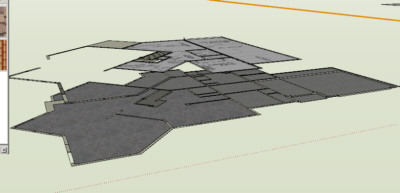
before we begin
let me stress the importance of a "Tidy Drawing"... Layers, Groups & Components... make sure to use them often and make sure to not to rely on the Hide command very much. Hide should be used to hide geometry lines, not things you are not working on. having everything on controllable layers and groups will allow you more control later when the model becomes larger and harder to deal with. the ability to work on specific areas will make your life much easier and make exporting your drawings much easier later on down the road. so when you build something, check it's layer and get into the habit. when you group something, go back and name that group in the group list window. this will allow us to view as much or as little of our plan at any given time, while leaving them connected, although you might find it easier to not only make Level 001 Layer but also a Level 001 Group so that you can move it around with out destroying vector lines. that's your chastisement for the day....
a word about detail. from this point on you need to decide your detail level, from here you could start building the rough framing for your house and putting it on a separate layer... if you go this far and even farther by setting a value for material you can use your model for very accurate take offs. I use it regularly for concrete volumes and roof square counts and tile counts and so on. for this example we are just going to build the wall shell for visual walk through.... now on to the lesson.
Step 1.
turn off all layers Except the Level 001.
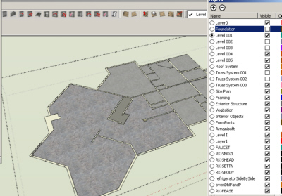
Step 2.
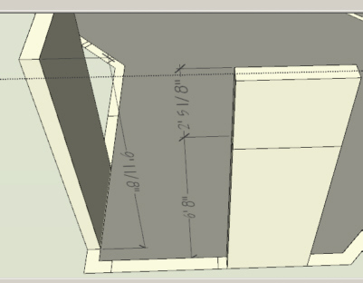
extrude, or push/pull all of the walls up 8' 1-1/8" or 9'1-1/8" or so on for what ever top plate line you intend.
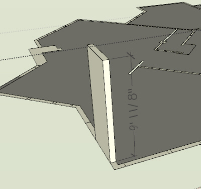
Step 3.
now extrude each door and window section up the blue axis 6' 8". this will be our door or window opening.
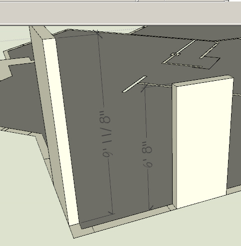
Step 4.
now extrude a new face up again to the top of the plate line. if you chose 9' 1-1/8" plate line, then it would be 2' 5-1/8" this will leave you a header area, and now is the time to think about transoms.
Step 5.
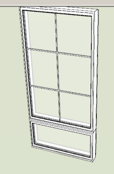
now is the fun part. time to find or preferably build some door and window components. search the internet for real door companies like Pella, Anderson or in my case for this project Peachtree http://www.peachtreedoor.com/products/windows_casement_500.asp. now click on the lower right-hand corner where it says size chart. here you will chose a style and size. use the numbers at the top and side to build your components and also to name them, that way later they will be easy to use again. if you're lazy or just want to be like us kool people you can purchase components from places like http://www.FormFonts.com
Step 6.
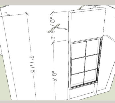
insert your windows and doors at the appropriate level. make sure they are all on our current Level 001. make sure that while you are inserting the doors and windows, that you don't delete the side lines from top plate to bottom. this will be needed for the floor plan sections we will export later.
Step 7.
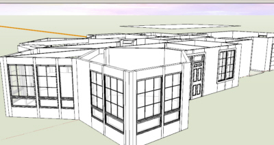
Repeat Step 3, 4 & 6 on your other levels. be sure to assign them to their respective layers and groups.
Step 8.
restrain yourself from adding textures and furniture just yet. texturing and furniture layout should be seen as a reward to your for your hard work on the model, and leaving it until later will allow us to make changes to the structure if a problem should arise in our layout, with out redoing texture and furniture. only use it early if you need it for sizing rooms.
Step 9.
we should be starting to see a recognizable structure now.... let's go around and offset corners and exterior walls 4" or 6" for stone facades... also we can do our columns and other exterior attachments. again, layer these accordingly.
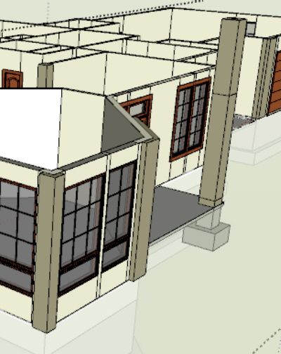
Step 10
now for the crème de la crème.
if you are building multiple copies of one structure or just want to watch your design as it is built. save each of your levels as components and then make copies of each level and stack them in order over in a "Viewing Area" in your model. and put it on a layer named "Whole House" now after you do this, you'll be able to work on each level independently and watch the changes over all on the whole house model....
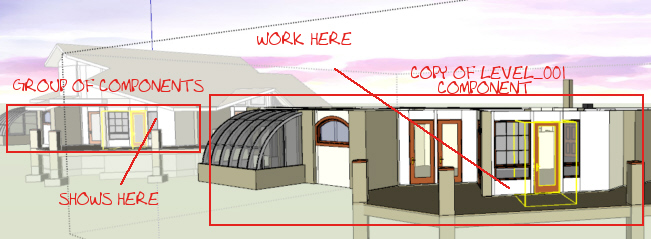
next time we'll add a foundation and a roof....
I'll add some screenies tomorrow...
if you are in the top view... square
and you have parallel view enabled...
and you still have this issue, I would say you need a better videocard or at very least to update your video card drivers...
if you are at scale already... then that's a videocard issue... if it's not to scale it may be clipping, to fix that a known GSU issue, you'll have to turn off the perspective view and use parallel view.
online...
after measuring a lined that you have drawn, you type in the box on the lower right hand of your screen, the measurment that you wish the line to become.
does that help?
Bigyin...
start a thread in the gallery and post your work as you go, people will stop by and drop encouraging notes and advice that you can't find by asking, the kind that pops into their head while they see your progress.
good luck.