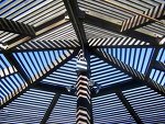
I didn't picture that at all when you said "rectangular grid".
@mac1 said:
Unless the actual building is racked some way other than just model errors the rendering issue should not be of concern ( can be handled be monochrome during design and the only rendering during show and tell, use of scenes, layers) and of course you have already accepted impact of schedule and cost have been considered since design change is not allowed.
BTW it takes 6 degrees of freedom to define the location of a rigid body in free space ( x, y, z, pitch, roll, yaw) etc. and SU allows you to do that and not with standing model errors fitting should be doable. Also BTW just translation and rotation gets different results depending on the sequence
I have to read your posts about 5-6x before they start to sound like English to me. Are you saying; 'the issues shouldn't be a big deal if I'm just rendering, not constructing in real life', and stating how much space I would need btw parts to actually build? Is translation the trick with going into scale, then typing "-1"? what do you mean by the diff results?
@mac1 said:
Attached is a approach that does not use rotate nor scale but just offset tool and the push pull.
Several additional comments; One snippet of geo 852' off set from main model deleted; architectural units display precision is not adequate for accurate modeling IMHO so changed to decimal;
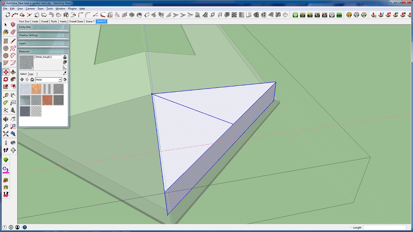
Su has the native capability of replacing one component with another and the replacement is added to model in accordance with how the new component and model axis are set.Both of those can be independently set plus the gluing plane can be set. This can allow the use of one component definition for all the lite's if model conditions are correct. (This is based on the fact component definition is invariant under scaling, rotation, moving but for the reason above this condition could not be meet.(The roof base triangles are not equilateral)
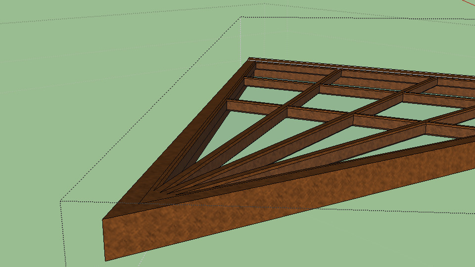
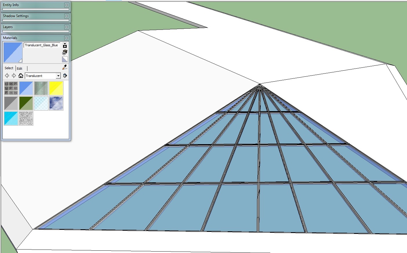
The attached portion of the model was simply done using the same Lite layout as the OP model and then the window frames will be created by a combination of off-setting to the required OP frame dimensions and the push pull to the required depth / height.
Double glazed lite's are required but only one side was done. IMHO a spider at top is still required to make the design reasonable as noted above.
While I appreciate the time and effort you put in to answering my q, I'm lost as to what you mean in the paragraph that mentions "geo 852'"(dunno what that is). I'm also confused as to what importing components has to do with the issue at hand. I think it would be easier to just redo the roof as I did, than to find/make new components to replace window panes. The main issue was not even the windows at all, the parts wouldn't fit bc the triangle was drawn wrong. Once I drew a good triangle, everything fit together. I know that windows can be made many diff ways, including push/pull, I made all the windows in my first model by dissecting a face with a plane and drawing every line by hand.
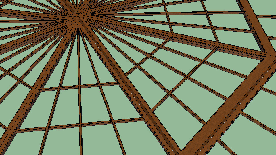
Now I'm smart enough to use a plugin, but that plugin was not working for the one window at the top. I was wondering if there was some reason that window wouldn't spawn, or what? even in the model you posted (2 copies of the same, right?), when I delete the lines separating the tip of that triangle above the row of holes you've cut, the tool will not make that face a window. Why not? Those were my 2 questions; Why no window, and why wont it rotate to match the mirror copy.
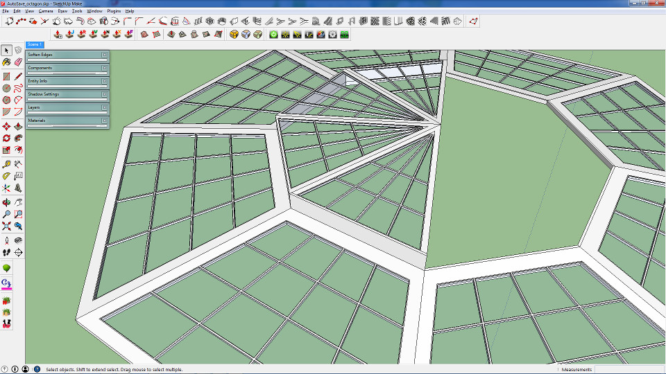
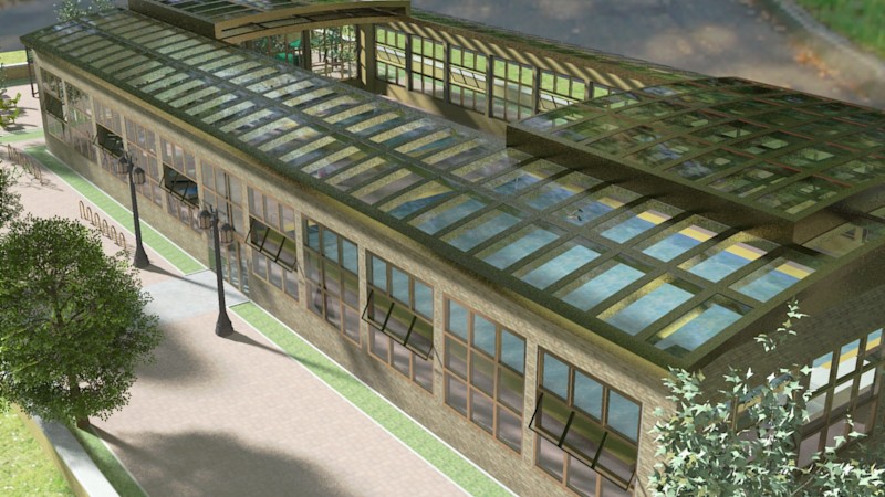
I now have that roof complete, the hard part was getting the 2 halves to meet in such a way that it would be possible for one side of windows to slide over the other, and I've represented that well enough to render(this isn't meant to be a construction plan). I'm still having trouble with the window frame tool. It refuses to work in certain areas, especially triangles. I've encountered a new issue, also. I've imported a few components, now my axes are all different. I cant draw rectangles on things bc the red/green don't line up with that component, so I must use lines. That or I wanna rotate something to match a wall, but it's not the same angle degree as the wall. For example: my wall is at 90deg. anything native to that group can be rotated to 90deg and fit nicely, but I gotta rotate this to 12.7deg or something stupid and hard to find. every component has a diff angle, like wth?? Is there a way to get them all on the same page, cuz it's a pain for me to rotate them just right, too easy to be off a bit.
As far as my progress, I wanted to stay with the look I had bc it went with the lower level of the roof, but yes, I did try a few styles when the first didn't work, you can see the new style has no equilateral triangle up top like before cuz the plugin wouldn't do it n I'd rather change styles than do all that by hand - I'm not "stovepiped" into any one idea.
