How do I create paralel lines trough two points?
-
Yes. Please supply a sketch of what you are trying to do.
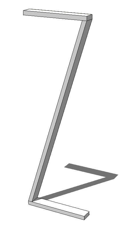
My guess, though is that you want to achieve something like I've done with the diagonal in this screen shot.

If that's the idea, the "Rotation by selection of plane and angle" tool in Fredoscale makes that very simple. You can get Fredoscale from the Sketchucation Plugin Store. -
How about just draw the edge and copy/paste it 25cm along an axis.
-
Have à look at the profile builder plug-in. ITS commercial but worth every Buck.
-
@unknownuser said:
If you need a picture I'll sketch something.
A golden's rule: for any question, join a sketch image(s) and SKP file if possible!

It's a time saver for anybody!

-
Clearly we didn't understand your question. I'm not entirely sure I understand your new one.
If you want a line that is parallel to the first but offset by 0.25m, you can drag a guideline off the first line and place it at that distance. Then draw a new line.
Or since V2016, you can use inferencing to place a copy of the line at the right distance.

-
Maybe I'm missing the point, but it seems easy to me.

-
@buggy b said:
... Let's say I have a face which is tilted or whatever so the red/green/blue axis are not helpful.
I have two points on this face. And instead of connecting them I want to create a line that "misses" the point by a specific distance (in this example 0.25m)I see what you are trying to do.
First of all if you do have that arbitrary face in space you can right click on it and select 'Align Axes' in the context menu. That would make the new drawing axes very helpful. Red and green are now in plane of the face and blue is perpendicular to the face. You can even rotate the red/green axes about blue to better suit your needs.
You are after a circle (blue dot is its center) with its (radius 25cm) forming a 90 degres angle with desired new edge or line. Try if by adjusting the axes you can get things working for you.
Your question has been asked many times. -
To those who apply a parallel line to a new one: I have no line in the first place, nor can I create one because I dont have point trough which a line goes trough yet. Only two point where each line goes trough only one of these two points. The question simplified in the second posting should make it more clear, but maybe I should have said the black line is what I want to create, it doesnt exist yet!
@Wo3Dan: Sorry if this question is asked many times, couldn't imagine a fitting searchterm for it. if I align the new axes to the face, how do I rotate it to the fitting alignment? If I had a line already it would be easy but yet I'm not sure how you do it.
-
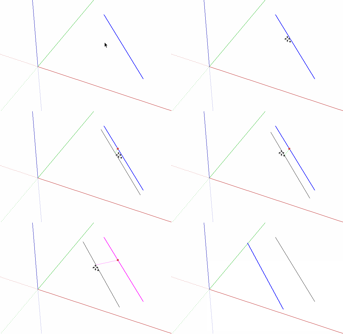
Okay I simplified the question:
Let's say I have a face which is tilted or whatever so the red/green/blue axis are not helpful.
I have two points on this face. And instead of connecting them I want to create a line that "misses" the point by a specific distance (in this example 0.25m)
(The black line has to be created, it doesnt exist yet!)
I'm not sure thos who gave first tips understood my matter, I will still look into the suggestions. Thanks!
-
@wo3dan said:
.....
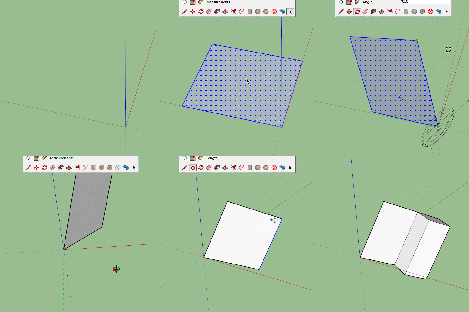
Your question has been asked many times.Hint: apply the 'Pie' tool as in attached image:
-
It wasn't clear at all that you have no line. Well, until you edited the post. Maybe you could provide a drawing showing a real use case.
You can use a circle with the required radius centered on one point and draw a line tangent to the circle and through the other point. TIG's True Tangents would help with that.
-
The problem I had with circles was they are not perfect, so the number of possible tangents is limited. But the plugin you mentioned sounds like exactly what I am looking for. Thanks! The others too for trying.
-
@buggy b said:
.....for trying.
Trying? All you need to do this with native tools is the 'Pie' tool.
Here's a practical situation Dave: (Jef once made a nice DC to resolve this but now SU can do it without plugins)
-
You are right, I misunderstood your first postings. With trying I meant trying to make me understand to solve my problems.

-
Gerrit, I know how all that works. I was just asking the OP for a real life example of what he is trying to accomplish as a way of getting clarification on what he's trying to do.
-
One more time if a simple Skp was linkded at the first post with a "before / after"
or "start / wished" inside how times and neurons saved!
-
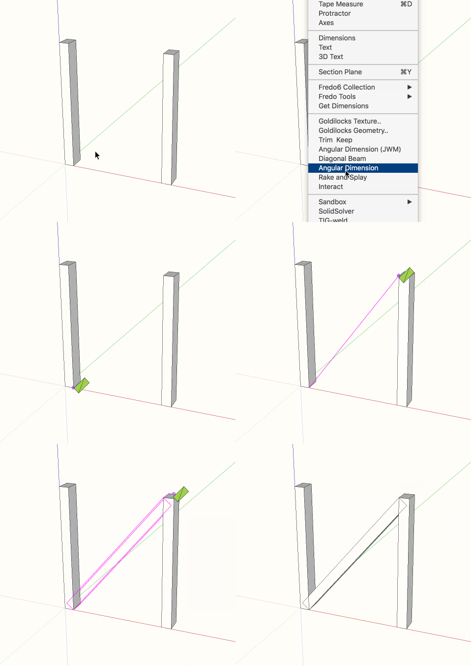
Here is an extension that I did a while ago but never published. It may solve your problem. It is designed for the situation in which you know the two diagonally opposite corners of a face of a rectangular beam, the beam width, and the beam depth. It solves the problem exactly without resorting to any of SketchUp's issues with polygons representing circles. This problem is in general not possible to solve directly via the SketchUp GUI.
To use it, click one corner, move the mouse to the diagonally opposite corner and click there. Then move to a third point in the same plane as the face of the beam and click there. Unless you enter a value the tool will assume you clicked at a distance from the second point equal to the width of the beam. Then click a fourth point to define the thickness of the beam. Again, unless you enter a value the tool will assume that this click shows both the thickness and whether it is in front or in back of the face in the view. You can enter both width and depth separated by either , or ; depending on your locale.
-
Here's a gif animation of the tool in use.

-
@slbaumgartner said:
Here is an extension that I did a while ago but never published. ....
Great plugin you got here. It must be a joy to (be able) to program in Ruby to get such "simple" new tools.
+1p.s. Dave, no doubt you know all that stuff. It was the image I wanted to post as a solution to "connect" your question (practical example) to what OP was looking for. More or less addressed to the wrong person.
-
diag_beam remember a cool challenge resolved by Fredo !
 (11 pages ! )
Advertisement


