Geometry size not consistent in SU 2015
-
I moved the model away from the origin a little to have clear access to the origin and then right clicked on it. If the axes had been changed, Reset would have been black instead of grayed out. There is some tolerance as in any drawing program. Sort of a close enough thing. Maybe you're running into that.
-
@dave r said:
There is some tolerance as in any drawing program. Sort of a close enough thing. Maybe you're running into that.
Maybe. But if that's the case, SU should be fixed by Trimble to properly handle this tolerance. Like not showing the ~ symbol when that's the case. Somehow is reassuring to see that is not so common issue, that means is something that i shouldn't be so concerned for other drawings. But still annoying that i can't figure out why it's happening here.
thanks all for the effort.

-
Every drawing program has to have some sort of tolerance setting.
It may not help but I don't see the ~ when I reduce the precision.

-
@dave r said:
Every drawing program has to have some sort of tolerance setting.
It may not help but I don't see the ~ when I reduce the precision.
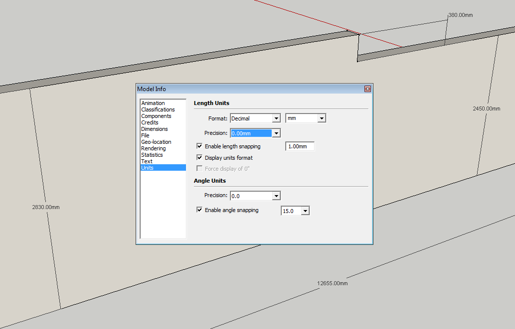
[attachment=0:1r3zxqoz]<!-- ia0 -->Screenshot - 6_13_2015 , 8_52_26 AM.png<!-- ia0 -->[/attachment:1r3zxqoz]That's what i was talking about...reducing precision places that strange symbol "~"
-
Do you see ~ in my screen shot anywhere? I don't see it.
-
There shouldn't be any issue with creating your geometry without ~ and to accurate dimensions.
Dave already mentioned that (some) faces aren't on axes planes.
At some stage you may have inadvertently moved some geometry slightly off axis.Use the 'Tape Measure' tool > disable the +sign by hitting [Ctrl] once > click on a large face with the tool to fix its starting point > orbit to get the axis color perpendicular to that face > now also hold down [Shift] and see how the values change when measuring locations on that face where they all should read 0.000000
I recreated your geometry next to yours, only relying on SketchUp's inferencing engine and estimated (your model) lengths to input. See attached model.
-
Thinking about this reminds me that another member had a similar issue a few years ago. Turned out he had managed to get things off axis somehow. It was only slightly but enough to show in the dimensions.
-
So if your object is not orthogonal it cannot have accurate dimensions? Really?
-
@pbacot said:
So if your object is not orthogonal it cannot have accurate dimensions? Really?
No, if the geomtery is accurate, the dimensions will be too.
-
@pbacot said:
So if your object is not orthogonal it cannot have accurate dimensions? Really?
That is not what I am saying.
But working with some geometry that is slightly off means that you should be extra cautious when expecting to continue collinear or coplanar. The axes may draw new edges on axisOf course it is possible to model 'not orthogonal'.
Also with geometry slightly off axis the 'Dimensiion' tool may indicate the ortoganal dimensions instead of the expected real edge lengths. Here again you can of course get the real edge lengths but SketchUp may trick you without bein noticed.
Thing is that the original model wasn't accurate anymore, maybe due to moving some edges or faces.
-
But is interesting how the geometry ended slightly off-axis when all of it was drawn using axis inference.
This was actually my problem... i know how to measure/check things... but I am still confused how can be possible that drawing parallel to axis can result in displaced geometry. And whats even stranger is that turning on ColorByAxis, all edges seemed aligned. -
Don't be bothered by that, Sketchup has its limits. Just be aware of them. The more you get into it the more you will be surprised(in worse)-especially when working with that much precision and small objects.
PS Make the habit of purging your model. There are plenty of components in the model that perhaps you don't want to share with everybody.
-
A couple of thoughts:
First, be aware that color by axis also has a built-in tolerance and will accept lines that are slightly askew. As a result, it is not useful for detecting small errors.
Second, (it may not apply to you) on a few occasions when I let go of the mouse to enter a value via the keypad, the mouse drifted slightly off the inference point. The line, while the correct length, was slightly off orientation. This makes the dimension come out with "~".
-
This model has many layers and some of those layers contain geometry that is not on the default layer. I wonder if some intersect or other operation could have caused this error?
I've seen some odd things happen when Sketchup automatically fixes errors upon saving as well.Only a thought.
Shep
-
@s shepherd said:
This model has many layers and some of those layers contain geometry that is not on the default layer. .....Shep
Yes, many layers, and oly two (+Layer0) remain after purging the model. I wonder what all the other geometry (in the now empty layers) was about. I guess the model was imported from some other cad program and already contained lots of little errors that you wouldn't get that easy with just SketchUp unless you use geometry from elsewhere.
I looked at the dwg imported floorplan and it has some thiny "off axis" errors.
-
@slbaumgartner said:
...color by axis also has a built-in tolerance and will accept lines that are slightly askew.
@wo3dan said:
@s shepherd said:
Yes, many layers, and oly two (+Layer0) remain after purging the model..
Thank you slbaumgartner, I was relying on ColorByAxis until now, assuming it is precise. I won't anymore.
Indeed, the model was part of a bigger model (a house model with many layers). The CAD outline I imported it afterwards. It wasn't part of the drawing. All other layers had geometry on the original drawing. I just cleaned everything off, to keep the element that was trouble making. All other geometry was perfectly aligned.
-
derei: Nothing in the digital world is precise. SU uses floating point arithmetic and it can not represent all the real numbers. For example, the legacy 32 bit systems 8 bits are allocated for exponent and one for sign and this results in the display precision of 7 digits.( That is 24 bit since the sign bit can used). When you select display precision in SU it has nothing to do with the internal accuracy. Why display was not changed when they went to 64 bits I guess was based on lack of need; The "snap to" is over ridden by input to the measurement box, but using is not helpful IMHO=> deselect and watch for the end point or intersection or other inference engine indications. Allowing a program to make unilateral correction without user control I do not do unless initiated by myself. Beore anyone comments I am aware error detection/correction is used every where

-
derie: Think you need to take a look at this step in the model:
<..... attached the original file - with the original axis orientation. Is part of a house that has a specific orientation, based on some topographic measurements and terrain.>
The model is " racked " some way + checking the evelation position shows confirmation of what Dave reported. I even confirmed there is no extraneous geometry causing the " problem". How and why that happened I have no idea but is high probability it is caused by OP. ( aka you). Before you proceed very far with model correcting now is a good idea??
FYI ref my post above: The 64 bits results in a almost 16 decimal digit precision ( 53 log (2) = 15.955 vs 7 one gets with 32 bits. -
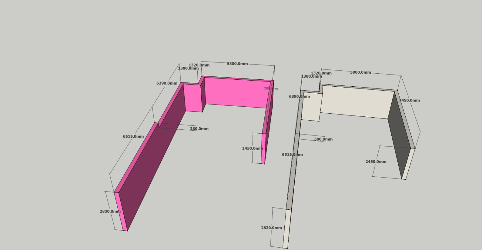
Derie: FYI The attached pic shows both the orginal on left and your problem model on right. Each is locked in my skp. You posted model was flattened, then used PP to extrude up to height shown in original and dimension shown at same display resolution for each. As can be seen both correlate. This approach basically replicates your model and one would expect both to be same. However, if the contention SU randomly changed model it seems reasonable errors in x,y which is not case. Detail look at steps in model creation can hopefully find where error was introduced.

Advertisement


