Faces on faces problem
-
Using SU 7, I often import dxf files that are missing faces & have extraneous lines, something like this:
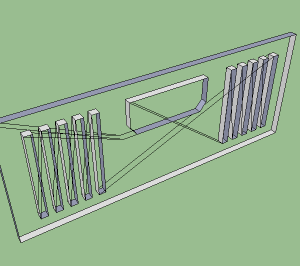
Oddly, the diagonal lines connecting the closed shapes are all coplanar with the front or back edges of the closed shapes, but do not "cut" any of the shapes' edges. For example, the rectangular slots each have just 4 edges front & back, even though the diagonals intersect those edges at various points. This by itself isn't a problem; I simply erase those lines before trying to add the missing faces, so I have something like this: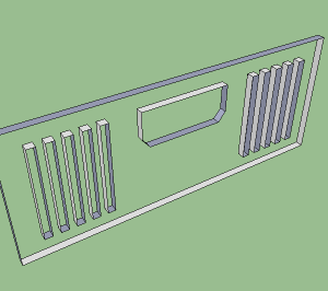
To do that, I start adding lines connecting the closed shapes. That's where the problems begin. As shown below, adding two lines creates two faces, but only one of the closed shapes is cut out of the larger face: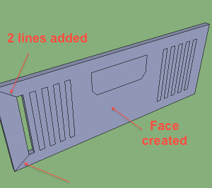
To create faces for the remaining closed shapes so I can cut them out of the large face, I draw a line connecting two of their vertexes, but this only creates one new face:
not the two I expect:
This makes it impossible to cut out the openings for the entire shape while retaining the large face that I want to have holes in it for those shapes. No matter how many times I subdivide the shapes with new lines, only one face is created at a time, leaving a part of the shape's face a part of the large face.Sometimes, I can select all the edges of the shape & use the "Create face" tool provided with SU as a plugin & successfully create the complete face, but sometimes this fails, & often the shapes have so many edges that this isn't practical, especially when the imported model has dozens or hundreds of missing faces.
I hope this makes sense, & that someone can explain why it happens & a practical workaround to deal with it. It only happens with some dxf imports, all of which pass the "Fix problems" step with no problems found.
Here is the skp file used for the examples, if that helps.Example.skp
-
I have not downloaded this, but have you tried simply tracing over any of the edges? Sometimes this will cause the faces to fill out.
-
Tracing one edge of each loop works for me. But first I ran ThomThom's CleanUp to remove the extra lines. Might be the same if you remove them "by hand".
But for this model I found a faster way. After cleanup, I traced one outside edge to get the overall face. Then I selected all and copied. Then I pasted in place. The interior faces all came in separated.
-
It erased the diagonal edges, which were clearly not needed.
Then I 'selected all' and used a 'add faces to edges' tool [there are several available, I have my own, unpublished].
Then I selected/deleted the faces to leave the holes...
I finally reversed/oriented the object's faces, as it was made 'inside-out'...
-
I had not tried tracing over edges, thinking that might somehow lead to problems because of multiple lines overlaid on a single edge, but at least with the example I uploaded, it works perfectly if I am careful to trace from one vertex to another -- the traced line & the original merge into a single line.
It also works if I just trace from a vertex to a point on the edge somewhere short of the next vertex, like to a midpoint, but that leaves the edge segmented with two end-connected parallel lines.
I'll have to see what happens with other models, especially those that already have edges made up of more than one end-connected parallel lines after import, but I think you have solved my problem.
Thanks!
-
@pbacot said:
But for this model I found a faster way. After cleanup, I traced one outside edge to get the overall face. Then I selected all and copied. Then I pasted in place. The interior faces all came in separated.
Oddly, that only partially worked for me. It only created two new interior faces:
Maybe that was because I removed the extra lines by hand instead of with a plugin?
-
<[quote="livemixer"]Using SU 7, I often import dxf files that are missing faces & have extraneous lines, something like this:>
...If you select one of those extraneous lines you will note it is not segmented as you would expect. Change your model units precision to .xxxxxx and use the text tool and you will note a very slight ~.00003 difference in the x dimensions between right and left even thought the edge display " color by axis" shows all at least parallel to the green axis.
I used the move tool so difference is .0000, used the make faces plugin and all faces formed as I would expect. Of course I had removed the extraneous lines as noted above.BTW the way I made the changes: Selected the right end of large rect and moved so error is zero; selected the right or left slats as a group and moved bottom ends to zero error; never touched the window. This made the large rects four corners zero error but the slats bottom zero and tops still with the same error=> tops tipped in. I tried face formation twice and worked ok. Why ok now? I have guess but too much analysis to prove.
You MAC may not work the same because possible difference the operating system numerical accuracy. TIG maybe can answer. If it does not then try correcting alignments in total.
-
-
@mac1 said:
Change your model units precision to .xxxxxx and use the text tool and you will note a very slight ~.00003 difference in the x dimensions between right and left even thought the edge display " color by axis" shows all at least parallel to the green axis.
I used the move tool so difference is .0000, used the make faces plugin and all faces formed as I would expect. Of course I had removed the extraneous lines as noted above.Very clever! I always suspected that some kind of precision issue was at the heart of this problem, but I never thought about using the text tool at max display precision to explore it. Thanks very much for that tip -- it will come in handy for exploring other issues as well.
Once you called my attention to it, I noticed there was also a similar x axis difference top to bottom everywhere except on the vertical edges creating the leftmost outside face, so some of the endpoints were offset as much as .000006" along the x axis from those reference points (2.250000" for the front edge & 0.750000" for the back one). So I guess the moral here is to pick one reference point & use it for all the endpoint moves one wants to be aligned perfectly along an axis, right?
What I find most interesting about this is that the trace line technique works even though the edges are not in perfect alignment. It somehow causes all the connected edges to "snap" into alignment, at least if they are close enough to aligned to begin with. I have no idea what tolerances are involved for this to work reliably, but judging from my model I'm guessing it must be greater than .000006". Any thoughts on that?
-
@livemixer said:
What I find most interesting about this is that the trace line technique works even though the edges are not in perfect alignment. It somehow causes all the connected edges to "snap" into alignment, at least if they are close enough to aligned to begin with. I have no idea what tolerances are involved for this to work reliably, but judging from my model I'm guessing it must be greater than .000006". Any thoughts on that?
there's a tolerance built into sketchup which will allow faces to form.. i never explored enough to find where exactly the tipping point is but i know it's there..
but, if you take your model then scale it up a few hundred times, you'll get the 'there's a problem in your model.. should i fix it? " (depending on how your prefs are set up)
in which case, sketchup will add hidden lines in order to break the surface down into multiple surfaces which fit inside tolerances
-
example --
i formed faces on the model then scaled it up 1000x.. then tried to save it which is one way to trigger the 'don't panic' message..
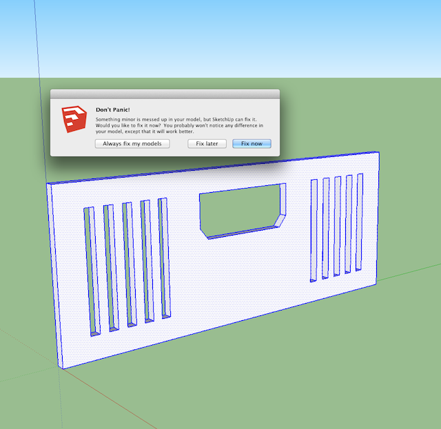
so, since the scaling has caused the minuscule errors to become larger errors, here is the fixed result :
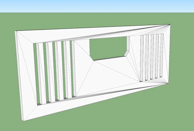
point being -- be very wary of bringing in models from other software.. ESPECIALLY if you didn't draw it in the other software and convert it yourself..
i always redraw DWGs that i'm given by architects etc.. It may seem like more work but once you start finding these tiny errors in their files, it becomes much more work fixing them instead of just drawing it fresh..
-
another popular sketchup rant / bug report is "intersecting faces sux! sketchup doesn't work right!" (or whatever).. but the reality is the user has a bad model but they're trying to blame sketchup..
here's your model with faces and not scaled.. i will intersect the orange box with the existing..
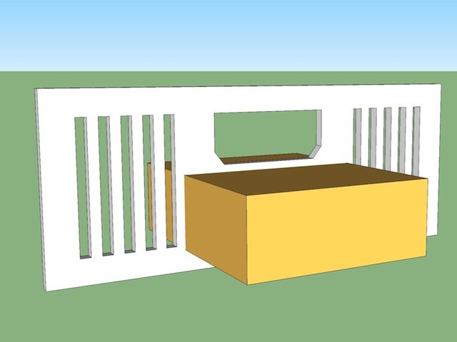
so now, since i've divided the face up into smaller pieces by way of that intersection, i've messed with the face forming tolerance (i.e.- on the non intersected version, the face was still forming because it was out .0005" over a length of 6'... but the intersection has caused it to be out .0005" over a length of 2' which is outside of tolerance .. (i'm making these exact numbers up.. just trying to get a point across))
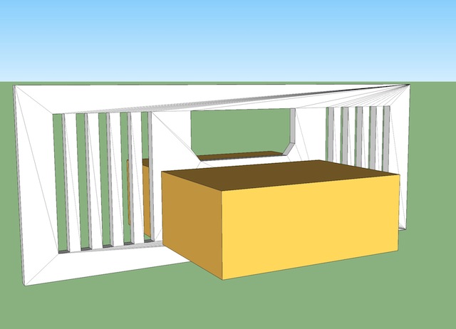
-
@unknownuser said:
another popular sketchup rant / bug report is "intersecting faces sux! sketchup doesn't work right!" (or whatever).. but the reality is the user has a bad model but they're trying to blame sketchup..
I think there is some justification for blaming SU. For one thing, it's a bit silly that the tolerance for creating faces from nearly aligned edges is below what the app can display -- I've tried zooming in on models like my example to extreme levels & never reached a point that shows that the lines don't intersect. Scaling the model up by extreme factors helps, but there is always still some minimum distance below which this becomes a problem.
At the least, the display should always be zoomable in to resolve the minimum distance the app supports. Anything below that should be considered the same point & all points in that neighborhood should be merged into one vertex without users having to do anything to cause it.
As it is, it seems that at least sometimes the maximum available display precision is greater than the precision of the underlying calculations, & that is more than a little silly.
-
Why should one be able "see" an error like this? On command SU should readily flatten or straighten to grid without the user having to study the intersections visually. It also seems silly that to draw something (macroscopic) one should need to, or want to, observe every corner at (virtual) microscopic levels.
Imported dwg from 2d applications has the same issues, though probably not as bad. So is it a CAD user error, CAD application or dwg format shortcoming or SU improperly importing the file? And SU not being able to fix it is worse. The plugins don't work that well on this either. Best is to simplify and cleanup everything before importing. Of course for a shape like this it could be drawn-up rapidly.
-
@livemixer said:
I think there is some justification for blaming SU. For one thing, it's a bit silly that the tolerance for creating faces from nearly aligned edges is below what the app can display -- I've tried zooming in on models like my example to extreme levels & never reached a point that shows that the lines don't intersect. Scaling the model up by extreme factors helps, but there is always still some minimum distance below which this becomes a problem.
At the least, the display should always be zoomable in to resolve the minimum distance the app supports. Anything below that should be considered the same point & all points in that neighborhood should be merged into one vertex without users having to do anything to cause it.
As it is, it seems that at least sometimes the maximum available display precision is greater than the precision of the underlying calculations, & that is more than a little silly.
nah.. there's no way our screens can show the real precision.. sketchup can calculate down to a millionth of a millimeter.. our screen can't come anywhere close to that type of precision.. and even it it could, our eyes could never ever see it without using some high powered microscopes..
if you have 96ppi on your screen then you're looking at each pixel being ~.3mm across.. no where close to .000003 which sketchup has.. and you'd have to zoom in x100,000 in order to start seeing any gaps..
but sketchup has a good inference engine.. i've never.. and i mean never had this issue pop up when i use it's inferencing to create a drawing.. it's inferencing works at least as accurate as it's tolerance and that's what is important here..
the other issues are user mistakes and sloppy modeling..**
[edit] **..well, it's not really fair to say it that way.. there are plugins such as artisan that are moving so many vertices around which will eventually lead to one moving such a tiny amount that you could end up with an invalid object resulting in the "don't panic" message..
so things like that aren't user error.. they aren't ruby writer error.. they're just things that are going to happen eventually when all things are considered.. -
@pbacot said:
Imported dwg from 2d applications has the same issues, though probably not as bad. So is it a CAD user error, CAD application or dwg format shortcoming or SU improperly importing the file?
too many factors..
but for one.. the cad apps might have been drawn at higher tolerances.. in rhino, i could set my tolerance to say, .1mm then go on to draw something.. so everything is good and valid within that tolerance but if i put the same drawing into something which is using smaller tolerance levels then there's opportunity for problems.. whereas if i could control sketchup's tolerance then set it to .1mm ,then everything would be fine..
(and we're not able to adjust sketchup's tolerance.. it's set.. we're able to adjust the precision to which it's displayed to us.)
-
While Sketchup has a good inference engine, I can suggest one way to force a failure to generate faces:
Last night I was drafting a floor plan in Sketchup, drawing lines on a very large rectangle on the ground plane. Using various inputs including use of guides. When I reached a stopping point, I decided to delete the underlying rectangle. There were plenty of faces not formed. I was using the inference the whole way. Occasionally faces didn't form due to line overshoots because, instead of using a guide, I just drew a line out to the general area where another was going to intersect.
I actually went through the process of selection and intersection on the base rectangle, Sandbox Drape, Superdrape, and ThomThom's Cleanup tools. After all of that, what solved it was the traceover routine.
It was like the drafting completely ignored the rectangle beneath it.
The above methods may not be the recommended workflow, but it demonstrates or hints at the precision question. -
oh.. right.. that whole tracing on a face thing..
are the vertices actually being placed in the wrong position though? or is some other problem within sketchup which is causing the face not to form?
next time that happens, set the accuracy to .000000mm then measure their heights to see if they were improperly positioned..
but i think the numbers will be accurate and that your example has to do with sketchup sometimes having problems forming a face on top of face (or forming a face in general at times).. which is different than faulty inferencing..
-
I cannot answer the placement of vertices question. I have seen this stuff often over the years. And, I work with no profiles or endpoints displayed.
I will check that-- Yep, I just had the default "precision" on. You only get 3 zeros max. My template is basic, feet and inches. -
Yes, over time I have not gotten a great deal faster, but learned to be more careful. I am mindful of being accurate, or trying to be precise, because small errors become cumulative, and somewhere down the line you will be wondering what went wrong and where, only to discover it is everywhere. You would need some hellacious plugin to make a global, one button correction for loose practices.
Advertisement


