I quit sketchup because of follow me.
-
The Follow-Me tool does quite a lot of guessing to work how it works (orientation etc.). It's especially difficult if your path is not precisely connected to a face or has gaps or very acute angles or it crosses itself...
Have you at least once searched the Help Center? Try out the "preselect" method, select first the path, then the follow-me tool and then click at the face. I hope that helps!
-
@unknownuser said:
As you can see I got it to work once, but the next attempt is another disaster. I've tried everything and nothing works. I quit learning sketchup because of this. And will again if someone can't tell me why it doesn't work 99.9% of the time.
A bit childish isn't it?
As you say you are in a learning curve, I suggest you to open the instructor window, and take some time to read sketchup user guide.Then report what's going wrong, just saying it does not work means nothing. When you'll know how follow-me works you will see it does the job.
Have a good day.
-
Since you've decided to quit learning SketchUp because you don't understand how to use one simple tool, there's probably not much point to the following. Here goes, anyway.
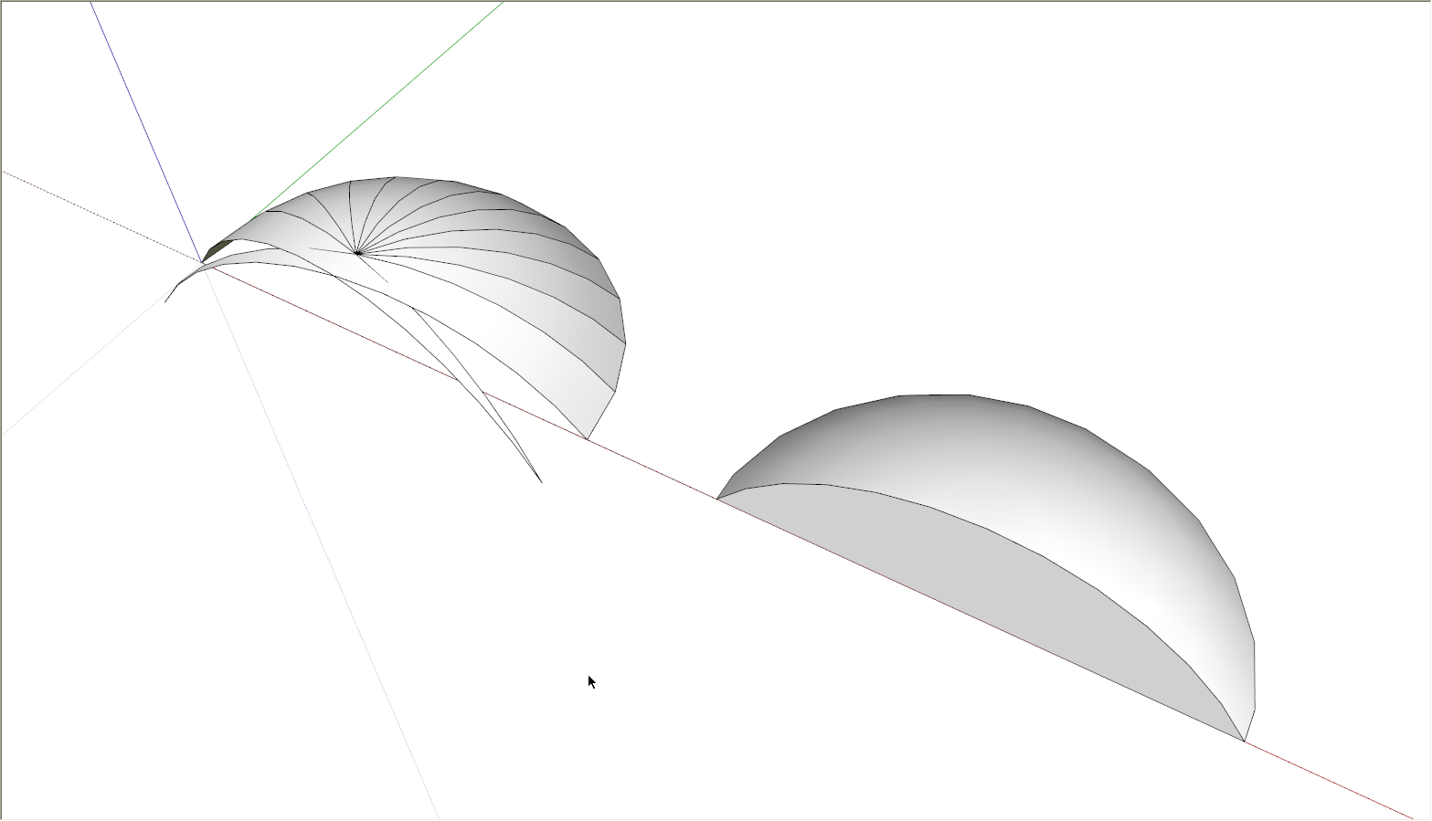
You comment demonstrates that you simply don't understand the way the tool works. As has already been written, if you'd actually take some time to learn how the program works, you would be miles ahead.
I duplicated your results by setting up something similar to what you had. the profile was not drawn perpendicular to the first segment in the path. SketchUp requires that to correctly make the extrusion. A simple change to the setup (on the right) makes all the difference.

Notice on the right, the first segment is perpendicular to the profile unlike what you had drawn. The reason it worked in the outer extrusion you made is that the profile and path started out perpendicular to each other.
So now that you've given up on SketchUp, what will you do with your free time?
-
Just Rotate your circle
(64 segments by 2.8°, 36 segments by 5°, 24 segments (circle by default) by 7.5°, 12 segments by 15° etc...)
for have perpendicular segments
-
The follow me tool will "project" the face that you use as a profile perpendicular to the path (in this case the arc segments) and will extrude the shape that way. What you show is a typical "feature" of the follow me tool when making half domes. Briefly speaking; the tools works as advertised and works correctly - but in certain cases it creates results that are not what we like.
For this scenario, there are two workarounds:
- One is (as pointed out above) to draw the arc with an odd number of segments (or rotate a circle in a way that it's end segments are perpendicular to the diameter cutting edge if you wish)
- The other one is to do a full dome, turn on hidden geometry and delete half of it.
-
Hi folks.
@gaieus said:
The follow me tool will "project" the face that you use as a profile perpendicular to the path (in this case the arc segments) and will extrude the shape that way. What you show is a typical "feature" of the follow me tool when making half domes. Briefly speaking; the tools works as advertised and works correctly - but in certain cases it creates results that are not what we like.
For this scenario, there are two workarounds:
- One is (as pointed out above) to draw the arc with an odd number of segments (or rotate a circle in a way that it's end segments are perpendicular to the diameter cutting edge if you wish)
- The other one is to do a full dome, turn on hidden geometry and delete half of it.
Personnaly, I always use the second method. Its is faster and less prone to error.
I use it a lot for piping elbows, for example. I create a full torus and then keep only 1/4 of it as a 90° elbow or 1/8 for a 45° elbow.
Just ideas.
-
Anyway, mICHAEL, yes, I, and I'm going to go way out on this one, everyone else is often/occasionally frustrated by follow me and/or other quirks/unknown ways of SU. Working in isolation with no work-arounds, one might be inclined to quit. But we need not work that way; we can ask others who share our dilemmas. Sometimes, usually, they will help. Sometimes they are slow to take the bait, do our bidding, agree wholeheartedly, and this too we have to live with. Sometimes they snipe a little too quickly. There's not much to do about that; they are more likely to help, and help a lot.
Me, not so much.
That the face must be perpendicular to the circle might easily get lost (perp to a circle?), but as we see it is critical and in the help on the tool's use.
@unknownuser said:
You can use the Follow Me tool to create full lathed shapes using circular paths. To create a lathed shape:
Draw a circle whose edge will represent the path. Draw a face perpendicular to the circle. The face does not have to be on or even touch the circle's path. -
So Pilou's example shows it is completely understandable to be frustrated by this tool: his face is in no reasonable way perpendicular to his circle?
-
Hum hum

The circle is on the flat ground, the face of the profile form is vertical!
So they are perpendicular!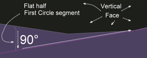
-
I would say that the face is perpendicular to the ground and to the plane of the circle, but not to the circle itself. But I accept yours as an explanation of why it works for your case.

Still, I say not so tight as is implied by 'understand and abide by the rules as stated and all will be revealed.'

Unless, perhaps, the usage were clarified to
@unknownuser said:
Draw a circle whose edge will represent the path.
Draw a face perpendicular to (the circle or to) the plane of the circle. The face does not have to be on or even touch the circle's path. -
Utter Gibberish.
-
You can cut the circle after its rotation for keep the segments perpendicular

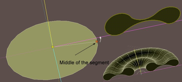
-
@unknownuser said:
to draw the arc with an odd number of segments
I am affraid that the segments of extremity will be not perpendicular!

Arc of 25 segments 93.6°
(Arc of 24 segments 93.7°)
Arc of 23 segments 93.9° -
Partly this issue is due to follow me requirements (answer: get Profile Builder). Partly it's about working with SU arcs. True arcs would not give the problem in OP's setup.
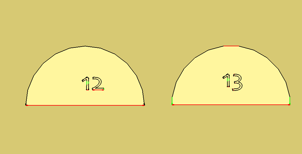
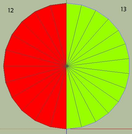
I wonder in regards to half arcs and quarter arcs, and even in respect to the cardinal points of circles why does SU draw them one way (Noted 12 in picture) and not the other (noted 13)? I know that segments of equal length are given for arcs. But is that really any use?
Both arcs are from the same circle, or (for SU) represent the same half circle.
What if every arc started with half a segment. Or an alternate (hold option key down) provided this feature? I think the arc marked 13 gives a better shape and can be more usable in drawing, if those were the issues. Would it break some rule of logic, geometry, or SU?
-
Assuming that the baseline is the same length, those two arcs do not share the same radius - the 'across the flats' version is slightly larger. This is because SU always takes the radius from centre to an apex - the standard arc has lines slightly within the drawn diameter, and No.13 extends slightly beyond.
Whether this matters probably depends on what you're modelling and what the purpose of the model is - but I think there does need to be a consistent method of determining the 'nominal' radius, for those folks who need to dimension their drawings.
A quick way to draw the alternative would sure be handy though. -
Actually they are from the same circle, so the base lines are not the same. So I see, the way SU defines the radius this would mean arc #13 would have other problems and an arch drawn with it would not dimension properly. I keep wanting to put "circle" and "arc" in quotes. The same issue we beat to death here, but not quite, regarding finding points that would easily be defined by a true arc.
-
Doesn't TIG have some plugin that draws arc in this way?
-
Sorry I must miss something!

How do you draw the "13" arc for have perpendicular segments without a rotation?
If you make a rotation, what is advantage to have odd number except kabalistic
I have not that!
(view top)
-
-
Advertisement


