Mini-challenge
-
@unknownuser said:
mac1
I was hoping it's already been established in the thread that the challenge isnt about accuracy from a real world construction standpoint. I mean, depending on the time of day (temperature) and humidity, a board will expand/contract far more than the results being given in the thread.We even use to calibrate our theodolites using a long Invar tape before making measurements so I am well aware of temps, ground movement, truck rumble etc etc.
Sorry did not read that I was working off your original post and I thought it implied a actual project working around walls etc.My last post gives the exact answer if you care about that. -
@unknownuser said:
Jason,
You're right.
The native Rotate tool seems to find inference in alignment of edges with others. You have to play around with it, but it seems to find it in the end.[attachment=0:24w854cr]<!-- ia0 -->Jeff Challenge3.gif<!-- ia0 -->[/attachment:24w854cr]
Fredo
I've been mucking around with this too; Fredo I can't replicate your 'parallel to edge'... which edge is it looking for?
-
@andybot said:
How is this different from gilles? (and I posted a similar one a ways back once I saw gilles method - by drawing a perpendicular to the diagonal). This still has an issue of not aligning precisely to the tangents. You can double-check it easily with TIG's true tangent ruby.
ok.. so it's not different.. it's just faster to draw it using a modified version of Moujiik's..
but.. here's something i figured out is different (and it's the reason you were able to get a perfect .000000" measurement in your file (which i missed until now)).. we (you and i at least) are doing something different than others in the thread.. we're working in inches..
.000001" is a lot more of a tolerance than .000001mm
so doing gilles' method in inches -- as long as your board doesn't get too wide, will in fact give perfect sketchup results (meaning smthg like 10.000000") even though it's still not perfect where as working in mm will still show the error..
so this is sort of interesting to say the least.. maybe because i never took the time to realize this:
**.000001 millimeters = .00000003 inches (that's 8 decimals)**so that means, anyone getting this within .000020mm has surpassed the accuracy which is possible with inches in sketchup..
-
Actually, the only reason I was using inches is because it's the native unit for SU. I was thinking I would avoid any possible "rounding to metric" errors. But of course, it all depends on scale, and mm will be a smaller scale giving a higher precision. In the end, checking against true tangent will show the error in any of the cases. (Except now I'm paranoid, maybe true tangent has some built-in approximation as well

 )
) -
@mac1 said:
..IMHO you really don't need SU.
you're right …
[flash=853,480:3ax8n44e]http://www.youtube.com/v/ww17dNJt_LQ?version=3&hl=en_US&rel=0[/flash:3ax8n44e]
… but where's the fun in doing it that way?

[actually, the second method in the video shows something that might make a good ruby.. 2pt orient with 1D scaling]
-
@andybot said:
Actually, the only reason I was using inches is because it's the native unit for SU. I was thinking I would avoid any possible "rounding to metric" errors. But of course, it all depends on scale, and mm will be a smaller scale giving a higher precision. In the end, checking against true tangent will show the error in any of the cases. (Except now I'm paranoid, maybe true tangent has some built-in approximation as well

 )
)yeah.. i'm sure true tangents would eventually show an error.. it just depends on how many zeros you can put after the decimal point..
which is basically what i'm getting at here.. if the people working in mm were limited to 4 decimal places, most of their results (the people using a gilles hybrid) would be showing a perfect measurement across the boardwidth even though we can tell, geometrically, there should be an error..
i think this thread is driving into some weird territory.. we're straddling sketchup's tolerances at amounts so small, it's hard to even imagine.. if this thread keeps going, we'll probably end up pinpointing the exact place where sketchup decides "this is ok.. and this is not ok"
[edit.. or actually, i guess that point is somewhere around 3 one-hundred-millionths of an inch
 ]
] -
I think I've found a very easy way.
Show you later, no time yet. -
-
Would be interesting to hear what the SketchUp team thinks of this challenge. ..too bad they are rather busy atm...
-
SUspense!

@unknownuser said:
actually, the second method in the video shows something that might make a good ruby.. 2pt orient with 1D scaling
And the same can make as option also Uniform or Stretch & Copy for the same price
 (Moi's function Line-Line)
 -
My True Tangent's 'True Intersection' tool uses Ruby's float and Math's functions, so it's probably as accurate as Sketchup itself in its calculated answers.
Sketchup has to have tolerance to assume two points are 'equal' because most likely they'll have some tiny differences in the 'zillionths'.
Any computational answer will never be entirely accurate - just accurate enough.
Because we are using sine/cos/tan/roots/pi etc we cannot expect a 'perfect' result.The calculated solution should be as accurate as needed to get a 'non-rounded' dimension at the limit of Sketchup's reporting.
Unfortunately the drawn solution's accuracy is slightly worse than Sketchup's reporting limit and so can show a tiny difference - the fact you can't even 'see' this in the real world is annoying.
With my rotation of the ends method gives a good approximation in one go, repeating it gets even nearer, and it might get so near that Sketchup then says it's 300.000000mm rather than 299.999999mm but it's a wasted effort in 'reality'. -
-
Thx for the V6

Must study your center rotation method because Step 4 is some tricky
FOr another method
I have thinking of use the offset for don't use rotation
-
Bravo Gilles !
At last a drawn solution [without plugins] that does indeed work with no tolerance issues !
Your very clever trick is getting the rotated 'end' to align with the 'long side' of its 'sibling' during the edit, it is effectively snapping to itself so the alignment is perfect... then both of the sides are parallel and the two ends remain the exact set dimension.

-

I can't make it snap to the endpoint when I rotate...
? -
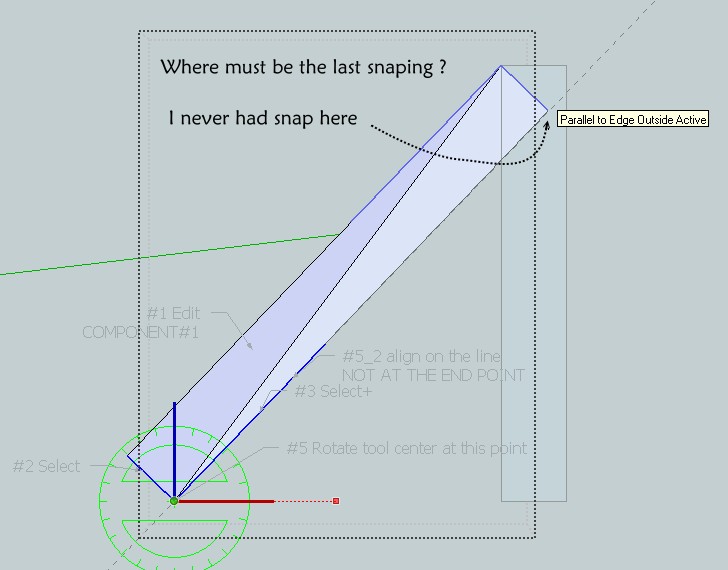
You don't need to snap to a point, click on the originally horizontal guide line, then it suggests an inference 'parallel to edge outside active', when you are approximately over the long edge in the sibling instance [as the ends are approximating to 'square'], click to accept that.

EDIT: As Pilou shows in his screenshot - pipped at the post! -
Seems there is not #4, ( there are two #5) and I can't obtain your last result

I have snap on Parallel but not at "point"

-
@unknownuser said:
I can't make it snap to the endpoint when I rotate...
Did you take the alignment point at the end of the line?
-
In Step 5 while snapping, my sketchup refuses to snap "exactly" on the endpoint no matter where I pick, are you sure it is exact?
-
I change the component axis location then it works better even with the end point.
Advertisement


