Sketchup is Inacurrate???
-
@thomthom said:
I've been playing with an idea of a cleanup function that will readjust vertices to be perfectly aligned - something that might be able to recover models that act badly, like some DWG imports.
That would be just the thing. Or make it like the solid inspector so it shows the problem and we can then manually fix it?
-
@unknownuser said:
......I think I may have missed an example model along the way so can you permalink me to the post which contains this solution you're talking about ? johns example which I remember didn't have any accurate arc points

fwiw, chord length between segments doesn't have anything to do with accuracy of an arc. and I can show you a few examples where you'll need oddball segment length which varies over the course of an arc.. what matters is that the vertices (no matter how they're spaced) remain a true radial distance from the cpoint.
You've got the correct model as I can see in later posts.
I know that there are minor differences, maybe even due to having things separated in groups. But the idea is good. That fact that they do not exactly share the same center if you zoom way in, yes you are right. But maybe this is due to speedy modeling to get the idea across. I stick with accepting this as a good offset solution.
And come on, segments not being parallel? so what? If I say corresponding vertices do not line up, then you say 'so what'. Sorry Jeff, in most offsets you can't have both at the same time, that is with arcs being segmented!. I left the idea of vertices being in line towards the center for what it is. I'm going for: all vertices on a true circle, equal segments (number can still be altered) and points at center in the same spot.And you can't be serious when saying that a chord doesn't have anything to do with the accuracy of an arc. Not on its own, but together with the defined radius there's only one arc on either side of the point at center, all vertices on a true circle.
The chord, together with the radius, defines the angle that is covered by the arc.How could the 'Arc' tool work if this weren't true: draw chord > specify (input) radius. Two possibilities as a result. Together one circumference of a whole circle, consisting of two arcs.
-
@wo3dan said:
You've got the correct model as I can see in later posts.
I know that there are minor differences, maybe even due to having things separated in groups. But the idea is good. That fact that they do not exactly share the same center if you zoom way in, yes you are right. But maybe this is due to speedy modeling to get the idea across. I stick with accepting this as a good offset solution.
And come on, segments not being parallel? so what?dunno.. my last post right before yours has the lines parallel as well as true arc measurements so it is possible.. that's all i'm saying.. you don't need to compromise in this situation.. you just gotta calculate it properly..
(re: parallel... i don't mean the segments of the arcs being parallel in john's example.. i'm talking about the straight edges leading into the arcs.. those are simple edge offsets and should be parallel)

@unknownuser said:
And you can't be serious when saying that a chord doesn't have anything to do with the accuracy of an arc. Not on its own, but together with the defined radius there's only one arc on either side of the point at center, all vertices on a true circle.
The chord, together with the radius, defines the angle that is covered by the arc.right.. the actual chord length of the entire arc is of course of utmost importance..
i thought you were talking about chord length between individual segments of an arc.. in which case, they're irrelevant.. i showed a picture a page or two back which had an arc drawn with all sorts of varying chord lengths amongst it's individual segments.. but it's still an arc in the same way as if it were equally divided and segments had the same chord length..
(i mean... you only need 3 points to define an arc.. the start and endpoints (or chord length if measured that way) then one single point anywhere along it's radius.. that 3rd point doesn't have to be in the middle - it can go anywhere which will created lopsided segmentation but it's still accurate)[but i kinda feel like you're just hellbent on trying to prove me wrong or smthng without actually looking at the various situations/models being discussed..
 ]
] -
@unknownuser said:
that's the only way i can figure out how to do this accurately without leaving sketchup.. but i also feel sketchup could be smarter and do the maths for us
I would call yours accurate, and to check it, I changed the arc segments on mine to 8 and they align perfectly...
when you've checked that, you can ask what plugin I use;] to draw th arcs.
john -
@driven said:
@unknownuser said:
that's the only way i can figure out how to do this accurately without leaving sketchup.. but i also feel sketchup could be smarter and do the maths for us
I would call yours accurate, and to check it, I changed the arc segments on mine to 8 and they align perfectly...
when you've checked that, you can ask what plugin I use;] to draw th arcs.
johnhey john
the amount of segments is irrelevant.. i just used 8 because it's easier to see where the vertices are..
changing yours to 8 does nothing to move the endpoints into their proper position.. (finding the endpoints in this situation is the only thing to be concerned with because sketchup can't do it naturally so you have to workaround.. all the other parts are easy to draw with native tools).. they should be 1000.000000mm perpendicular to the straight edges but they're not.. those straight edges on the left and right side should be parallel..re: plugin.. not sure.. me personally though, i always use didier's 3pt Arc.. (centerpoint,end,end) ...as in, i bet i use that plugin more than any other single plugin.. (actually, i know i do)
[edit] ie- getting those endpoints is not much different than that 20pg mini challenge thread a while ago.. it all boils down to sketchup not having real circles.. (and i don't mean real circles visually on screen, it's fine if they're segmented.. i mean it's brain doesn't have real circles.. so it can't find intersections other than straight lines crossing each other)
-
@unknownuser said:
they should be 1000.000000mm perpendicular to the straight edges but they're not.. those straight edges on the left and right side should be parallel..
I just used the given geometry, I didn't redraw the straight edges, [ I wasn't doing it as a pissing contest (@ that point)]
@unknownuser said:
re: plugin.. not sure.. me personally though, i always use didier's 3pt Arc.. (centerpoint,end,end) ...as in, i bet i use that plugin more than any other single plugin.. (actually, i know i do)
I know you use 3pt Arc.. and that's exactly why I did as well.
All I was trying to point out was if we can draw it that 'close to being' accurate, then the engine didn't need changing, it just needs exposing in an easy to use tool, either as an additional option or as a new tool.
The biggest thing that annoys me [other then you, of cause!], is the 'Offset Tool' doesn't snap on the arc point, so you can't be accurate with it.
john
-
@unknownuser said:
.....[but i kinda feel like you're just hellbent on trying to prove me wrong or smthng without actually looking at the various situations/models being discussed..
]
Sorry if you feel that way, for that is not the case.
Just a few misunderstandings. At one point (corresponding vertices not being lined up towards the center) I argued in your favor about John's solution. But you set that aside as not being important.
I don't much care who's right. It's all for a good second option in the 'Offset' tool, hence my little challenge. But Right now I don't think much of repairing the offset at its ends, something I supported at first
PO?,....... I hope not,........nah.p.s. my PC is acting weird. I can hardly keep up with all the examples that are being uploaded. Loading a model (even from HD) can take upto 5 minutes where it should only be seconds.
-
@driven said:
I just used the given geometry, I didn't redraw the straight edges, [ I wasn't doing it as a pissing contest (@ that point)
ha.. i'm not pissing contesting either.. we were just talking about accuracy for the past week or so in the thread so i think it's important (for the sake of this particular discussion at least) to be accurate..
@unknownuser said:
I know you use 3pt Arc.. and that's exactly why I did as well.
check out this plugin.. i did this huge workaround 10x faster than it took me to do the sketchup-only work around..
(no audio)
(**includes bonus footage of su's spazzed dwg importer)
that's the same model saved right after i quit ishowU_ing
that's not a plug in.. it's a plug out..
why would i want to use sketchup at that point? i wouldn't.. that was kinda my whole point up until page 20smthng when jbacus basically summed up the future regarding circles in sketchup..i guess now i'm just talking because i'm a nerd like that
@unknownuser said:
All I was trying to point out was if we can draw it that 'close to being' accurate, then the engine didn't need changing, it just needs exposing in an easy to use tool, either as an additional option or as a new tool.
The biggest thing that annoys me [other then you, of cause!], is the 'Offset Tool' doesn't snap on the arc point, so you can't be accurate with it.
nah.. the engine needs changing.. it needs to be smarter regarding circle.. there is no new tool that's going to solve this because it's the whole app being affected-- not just the offset tool.. teach sketchup some basic circle stuff and a whole slew of problems will start disappearing.. otherwise, all you're going to do with a new tool is pile more crap on top of a weak foundation.. fix the foundation .
(of course.. that is simply my opinion.. i truly understand that many people couldn't care less about this)re: annoying..
i annoy myself with this stuff too.. like i'm bothered that i'm even bothering any longer.. i wish i could stop but i haven't found the switch yet
-
@unknownuser said:
nah.. the engine needs changing.. it needs to be smarter regarding circle.. there is no new tool that's going to solve this because it's the whole app being affected-- not just the offset tool.. teach sketchup some basic circle stuff and a whole slew of problems will start disappearing.. otherwise, all you're going to do with a new tool is pile more crap on top of a weak foundation.. fix the foundation .
(of course.. that is simply my opinion.. i truly understand that many people couldn't care less about this)....I'm sure there are plenty of folks out there who wouldn't care about these issues, mostly the ones used to how SU works, because they are set in their ways.
Many have a problem with changing things to the better and settle for what they can get.
I think it would be a shame if SU would not evolve and I do see the great potential.I'm very happy that it did evolve to where they added the solid tools. These are a great asset in today's world of e.g. 3D printing and a step closer to making us build more accurate models. (and requires SU to be even more accurate)
So as we progress, the requirements and standards will also become higher. To not improve would be going backwards. I, for my part, would love to keep working with SU in a world that changes fast and be able to deliver great and accurate work for my clients. -
@Jeff
You must return make a little visit to the Moi Forum ! -
@unknownuser said:
@Jeff
You must return make a little visit to the Moi Forum !i did.. michael pretty much told me I'm dumb for using sketchup
not in a way that says anything bad about sketchup but more in a way of..
"hey, it's not sketchup's fault for not working that way.. it's your fault for trying to use it that way.. "
(actually, he didn't say any of that really... it's just the feeling i got after reading.. but if he did say exactly that, i'm thinking i agree
) -

Despite of all that, what is the best connection between 2 parts of any inclined roads on a flat terrain?
(in any progs of course just in theory with same width on the path)Compass+ Protractor + Set Square + Ruler
Arc circle + tangency
Blend + tangency G1, g2, g3...+ Bulge
Fillet G1, g2, g3...+ Bulge
Sweep variation
Conics
Offset of one jointure
From a joined yellow line then propagate a perpendicular width segment
...
(here connection wanted on the top)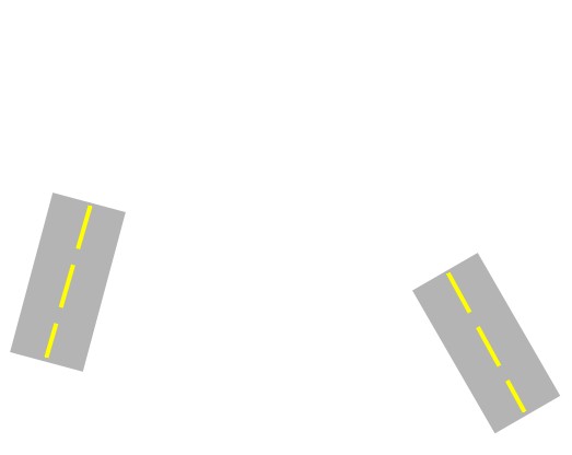
-
-
Robust!

And if for any reason I don't want elongate in straight line the piece of road on the right ?
-
@unknownuser said:
Robust!
And if for any reason I don't want elongate in straight line the piece of road on the right ?
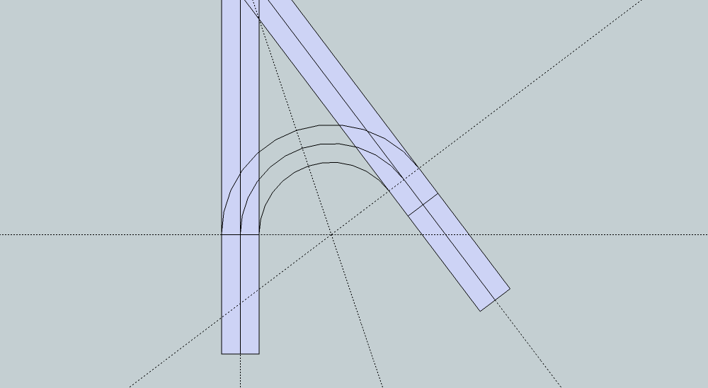
You then need to shorten the road on the left AND increase the radius !
There can only be one circle of a given radius that is tangential to two lines drawn line this, and it will determine its own 'kissing' points on these... Its center is always on the bisector of the edges' angle, and the circle can slide along this, and therefore depending on its radius that will fix the center, because it must be the radius away from both edges when measured perpendicularly from them... -

-
I have been following this thread. And I care, if it is do-able.
-
@unknownuser said:
You then need to shorten the road on the left AND increase the radius !
Robust again
So if for any reason I don't want elongate or shorter in straight line pieces of road on the left and the right connection with tangency is impossible ?
Said a "plumber" who has not straight tubes but any curvated one
-
@unknownuser said:
")
Despite of all that, what is the best connection between 2 parts of any inclined roads on a flat terrain?
This is a standard "OGEE" Curve problem of joining 2 non parallel roads.
Did it in High School (that's 53 years ago
) with pencil, compass, slide rule, protractor and ruler. No such thing as a pocket calculator then, let alone Sketchup.But damned if I could remember how I did it!!!

Played in SU for 29 min and got nowhere.
So the attached drawing is a "Sketch" of what the solution would be.
Not calculated, just by eye.
The "road" rectangles are drawn overlaid on Pilou's ROAD.JPG.
-
@unknownuser said:
Despite of all that, what is the best connection between 2 parts of any inclined roads on a flat terrain?
(in any progs of course just in theory with same width on the path)Compass+ Protractor + Set Square + Ruler
Arc circle + tangency
Blend + tangency G1, g2, g3...+ Bulge
Fillet G1, g2, g3...+ Bulge
Sweep variation
Conics
Offset of one jointure
From a joined yellow line then propagate a perpendicular width segment
...
(here connection wanted on the top)in sketchup, you can use bezierSpline to get a tangent b-spline for one connection.. as far as accurately offsetting that curve, i don't know how to.. the maths go beyond my knowledge at that point and i'd rather just have software do the proper calculations for me
(and actually, i don't know the maths to even see if the sketchup drawn b-spline is in fact correct.. and this is an instance where, to me, it's required that i'm using an app that i can fully trust to give the right solutions.. goes back to what i was saying about knowing the numbers.. i don't know the numbers here and neither does the app so i'm screwed..)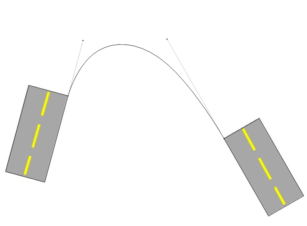
• draw an extended line to the one you would like to connect tangentially to..
• using uniform B-spline set to an order of 4 at least, make 4 clicks, (first tangent point, end of it's extended line, end of the other side's extended line, second tangent point)but assuming that curve is in fact correct, i have no idea how to proceed with offsetting properly (as in, arcs are easy to understand.. these types of curves?.. well, let's just say i was never taught about them in school..
but hey, in sketchup, i could definitely come up with something that looks ok..
Hello! It looks like you're interested in this conversation, but you don't have an account yet.
Getting fed up of having to scroll through the same posts each visit? When you register for an account, you'll always come back to exactly where you were before, and choose to be notified of new replies (either via email, or push notification). You'll also be able to save bookmarks and upvote posts to show your appreciation to other community members.
With your input, this post could be even better 💗
Register Login


Advertisement