HI and a question
-
HI, new to the forum.
I've been playing with Sketchup for some time now and I must say I very much enjopy using it.
There is an issue that I have, however, which I cannot resolve.
I realise that it must be a measurement issue, but I cannot figure out where the error is happening!
I have a building plan which I have measured to the inch. When I draw the outline, everything matches up from 'front to back' - i.e. the 'depth' of the building, is precise.
The building is two rooms which adjoin a central square.
I have measured the square four times, and have the measuremant to the inch.
When I then draw the plan, I am left with about 96 inches of 'empty space' over the length of the building.
For instance - if I draw 'from the back' and use the width of the central block to start, once I get round to the front door which is directly opposite, there is no space for a door: the space is gone.
If I draw from the front door - there is the same error in reverse (empty space).Since I have triple checked my measurements, I cannot seem to see where I am making the error in the program, since all windows and corners match up to the inch.
Any tips to trouble shoot this?
-
It would be helpful if you could post a screen shot or the model but...
From the description, the only thing that comes to mind is that your walls aren't square to one another. When you are drawing, are you using the Line tool? If so, are you drawing on axis? That is, when you are drawing across the front, is the rubber band line following the tool red? And when you turn the corner, is the rubber band line green? If you are having difficulty getting them to be so, I would suggest that you go to the Styles dialog (Window), hit the Edit tab and click on the left most cube below the Edit tab. This is for Edge settings. At the bottom there's an area for color. Click on the drop down arrow and choose By Axis from the list. This will color the lines to match the axes to which they are parallel. Check your lines and see what you get.
-
How thick are the walls between the rooms ?
Have you tries using the tapemeasure tool to offset some edges precise amounts ? -
HI Guys
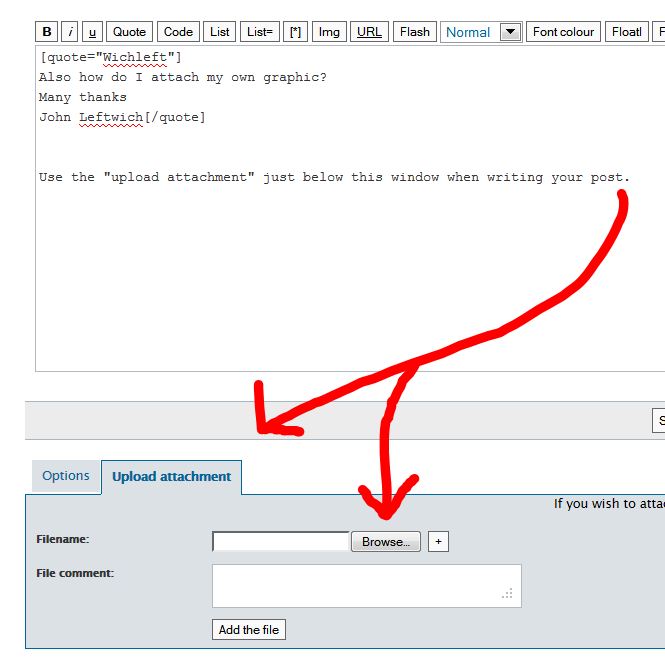
I've uploaded a screenshot.
What you will see is that the central 'square' has a missing section.
Now, I draw by line, and I know the rear wall mearsurements to the inch. As can be seen, these flush up to the 'square' which extends out by the amount shown.
Note that the square extends inward - the walls are aligned with the sides of the front entrance (front) as they are in real life.The issue is that, no matter what way I am drawing, I am left with this gap. Now I have triple checked the measurements (its 382 inches along each rear wall, and the 'square' is 308 inches.)
Yet when I reach 308 inches, this gap remains.
The only thing I think may possibly be an issue is the angle of the bay windows on the front?
I am sure this is an elementary thing I am missing but I cannot see it!

-
Could you post the SKP file?
-
Why not start off from the 'square court' and seek where it takes you.
If you are convinced of that forms accuracy start with that and see where the error is is what's left over...
If you have 'surveyed' the rooms carefully you ought to have taken the dimensions of the main rooms' rectangles - ignoring the bay-windows etc and add those on to the main rectangle, erasing unwanted lines as you complete.
Where are the wall thicknesses ?
Presumably you won't have two rooms adjoining each other with paper thin walls ?
This is not really a SUp issue more a surveying and drawing up problem ??? -
TIG,
It is losing 58 inches somewhere and it is me- not sketchup - but I cannot understand why.
I know my measurements are correct - but I will just close that gap for now and use what is - since I am totally happy with the rest of the model - perhaps it is an error I am doing on the computer and just not seeing it!

-
Why in the world do you refuse to post your simple model? The guys here would probably find the answer in secs or do you just to like to ask questions and in the process waste peoples time

BTw you can use the entity info to get a measure of each line length or the text tool and display the x, y,z value for each end point and quickly find the problem. -
mac1:
If you can point me where to post the skp to, I will.
-
From another thread.
-
-
OK...
Since we don't have any 'original' dimensions how might we know the 'errors'?
I have marked where you assume a paper thin wall, that will have a real thickness...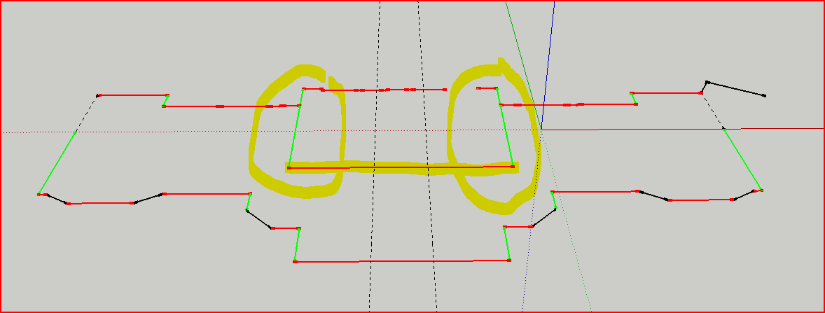
-
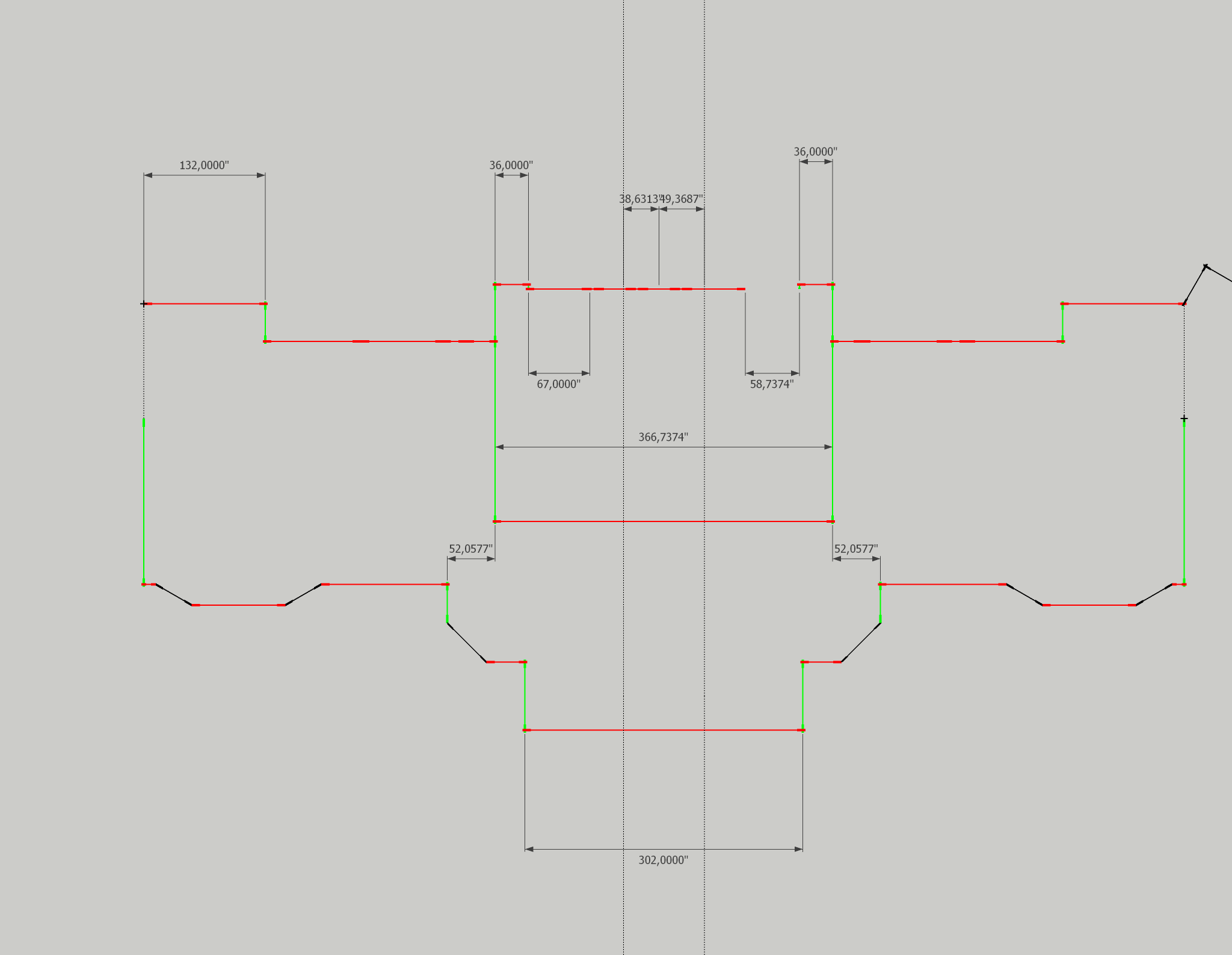
I am almost certain that no-one but you know what these dimensions should be. I suggest to start adding real dimensions to your floorplan and somewhere you will find the mistake. You can snap dimensions to anywhere: endpoints, midpoints, intersections (with guides for instance) to be precise. Somehow like this (I converted all dimensions to simple inches as my brain cannot work with feet & inches)
-
Tig,
Yes, there are lot of walls which are between 8 and 16 inches thick in the building.
The two lines in the centre are the entrance hallway (5'). The building is to the inch.
The 'square' is divided in two down the middle with a 6" wall. At the rear are two 42" windows, framed with 6" frames - exactly in the middle of the building opposite the front door (which is two 2.5' doors).
The rear walls join to the extension of the box at precisely 31' 10".
At each corner (on the rear of the square) it is 103 inches to the window frames.
The actual measurement is 103-6-42-6-42-6-103
You will see that the rear walls align with the front walls with an offset - this is correct - and you will see it is symmetrical as you would expect.
If I draw to here, and do not insert the 'square' - the whole building is perfectly OK - but the measurements I have taken (most recently a recheck on friday) doesn't align the 'box'.
-
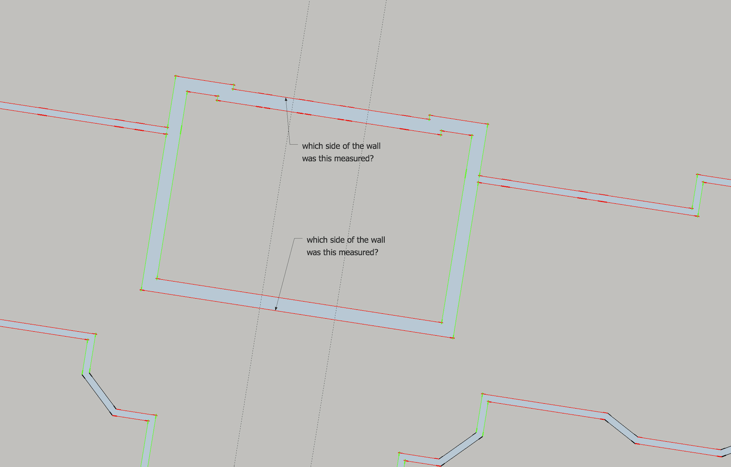
I could not help wondering what side of the walls were being measured. I drew in some walls-- arbitrarily in hopes of finding the discrepancy in a way that would be favorable (I made a further guess and extended the alcoves each side of the central square), but perhaps not enough length. So that's the question I'd have: If you draw in the walls, even temporarily, which sides of the measurement are they?
Sometimes in measuring a building we measure wall thicknesses at doorways. In conventional homes, to save time, I usually just assign the standard wall thickness when drafting, knowing that I want a "square" plan that ignores those as-built discrepancies that would be insignificant to the builders--then I might check it further against overall measurements. Either way, I draw the wall space into my site sketch. These things can be vexing, back at the office.
-
dom86;
One other thought. You are measuring an imperfect building and then modeling it perfectly. I have not done any analysis ,but form my intuitive thinking the wall thickness may not account for such a large error. The thought is a small racking of the building can give large errors over the long distances you are dealing with. If you have any chance it may help to measure some diagonals to get some idea how square the building is. I don't think you want to model on that basis but could help understand the issue. -
Guys
Thanks. I will pop another file up soon. I have discovered that what it seems to be is that the measurement on the front is off.
The two extensions off the main block at the front actually sit over part of the main building: this is the same on both sides - since I have measured outside only this is where the gap (seems) to be coming from - I will draw up an example
-
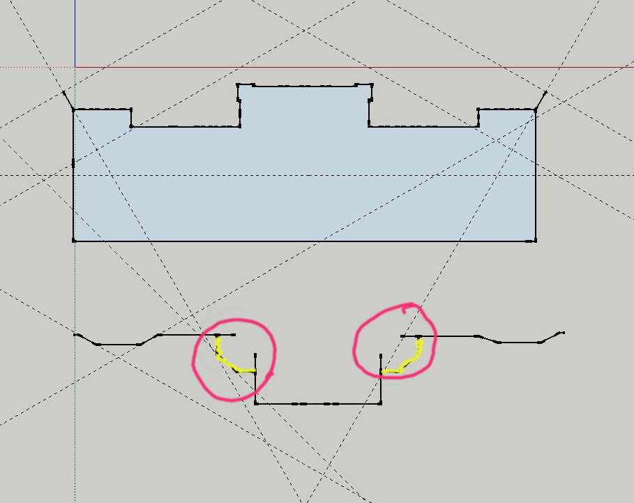
OK: I think this is where the problem is: I have 'counted' the distance around the wall (highlighted in yellow) - but as they are effectively bits that are 'added on' they are not part of the building itself, and what's more some measuring matches the discrepancy to the inch....
-
Some thoughts for you. Aligned square and front entrance per your 2 26 616am post and added double jack studs and trimmers for the two window case.
Just some thoughts.
u001_mac1B.skpdom86 -
Mac1
Thanks. I've had a look, my skp was not marked correctly from the window aspect.
I am now working an a new plan, but without side extrusions, it should look a little more accurate
Hello! It looks like you're interested in this conversation, but you don't have an account yet.
Getting fed up of having to scroll through the same posts each visit? When you register for an account, you'll always come back to exactly where you were before, and choose to be notified of new replies (either via email, or push notification). You'll also be able to save bookmarks and upvote posts to show your appreciation to other community members.
With your input, this post could be even better 💗
Register Login


Advertisement