Modeling issue: Cloth wrapped around a metal structure
-
Hello everyone, I'm a big fan of both SKP and the sketchucation community.
Sketchup rappresents the main part of my personal workflow, in fact from the 3D model I export the 2D which needs to be very accurate, cuz my goal is to draw nothing or nearly nothing in 2D.Most of the times when I have any sort of problem or need a clarification I come over here and find what I'm looking for. This time unfortunately it's just way too complicated to find exactly the solution to this 'cause it's a very specific problem. Therefore I decided to make a video showing exactly what's the issue and what I'm trying to acheive.
Posted right here.
http://www.youtube.com/watch?v=kdxZgqCnYY0&hd=1
[flash=640,390:302fdf2c]http://www.youtube.com/v/kdxZgqCnYY0[/flash:302fdf2c]
EDIT: I tweaked your code to also add the movie directly to the post. TIGI need to be as much accurate as possible, trying to find the BEST way to accomplish this task, possibly in the fastest way possible.
P.S. in the video I forgot to mention that I already tried to use "allign" and "offset" functions in the profile builder plugin, but since the profile is SO tangled up turns out to be just unusable.
Looking forward to know what you guys think about it! Thanks
-
Hi,
Maybe upload the cage for members to play with?
-
-
Hi,
Do you have just the line work of the frames? Rather than these lampshade shapes

-
Like I say in the video Rich, for compositive reasons I first modeled the "lampshade shapes";) and now I need to model the structure underneath. Turns out that the only linework that I have available is the one I posted, the same that I can't scale to fit in any way possible

The next attempt I'll try will be to draw in 2d a couple of sections and a top view and then start from there. I'll post the results!
-
Your object is achievable if you take a different approach.
Make an upper and lower ring of the cage using the line tool. Radius the corners with a 4 or 4s arc. Make a copy
Either handstitch or using one of several lofting tools skin the frame.
With the copy use line2tubes on the rings. Afterwards scale in red and green direction to suit.
This then can be tapered or sheared for the other objects so give each a different shape
-
You have got the tube making working to your general satisfaction ?
All you now need is the edges that are used to make the tubes inset by sat 25mm to suit 20mm radius tubes - so that they are wholly within the original distorted form's 'skin' [I suggest they should be inset a little like this, so that you don't get 'z-fighting' where the tube's edges might to be seen through the skin's faces].
Incidentally, setting View > Component Edit > Hide Rest of Model removes the rest of the stuff making it easier to see what you are doing...
Here's the way I'd do it...
Firstly you need to get a tool by Jim Foltz called 'shell' http://forums.sketchucation.com/viewtopic.php?p=292452#p292452
Get it and load it before restarting and using my method...
Edit a 'distorted-frustum' form.
Copy all of it to one side by typing say exactly 10m [so you can move things back later].
Work on the copied geometry.
Select all of that and make a group.
Edit the group.
Add additional faces so that the top and bottom ends are sealed and it is 'Solid' [manifold].
You can check that it is made so by exiting the edit and selecting this group and Entity Info should now say 'Solid'.
Select the group.
Use the 'JF Simple Shell' tool and in the dialog enter 25mm.
An inner 'shell' group is formed 25mm inset from the original.
Switch to Monochrome view mode [with a Style that has a noticeable color difference between default front and back materials] as it'll be easier to see which are the outer and which are the inner faces as you edit...
Erase the original outer group.
You should be left with the inner shell group [looking at 'back' faces], these are all inset 25mm.
Edit that group.
Erase the faces and keep the edges [remove any temporary edges that you might have had to add earlier to create the 'manifold' form].
Add additional diagonal edges to form the bracing lines etc.
You now have a set of edges inset by 25mm.
Select this 'cage' of edges.
Use whatever tool you prefer to add 'tubes' to them with 20mm radius.
Exit the group edit.
Move the group along the same axis as before typing in exactly -10m so it's correctly located back inside the original form's 'skin'.Done.
Obviously you can adjust the shell dimension to match whatever radius/diameter tubes you are intending to use etc.
With tubular structures the 'nodes' are always awkward - one suggestion is to make a sphere component with it's origin at its center, and when the 'cage' of edges is ready place instances of it at each node. It will mask the ends of the tube. If its radius is slightly more than the tubes' it should look better. The advantage of using a component is that you can edit one instance and scale it from it's center [+Ctrl] typing in a new value with a units suffix - say 75mm - and all instances will auto-update...
Another tool you could try that gives you rectangular frames is my 'LatticeMaker' tool.
It's similar to the latest 'Windowizer', but it allows you choose to have 'no' panes etc.
In this case you wouldn't erase the inner shell's faces, but you would need to 'reverse' them all so they face out.
This time the shell inset could have been set at say only 5mm as the outer face of the frames is the plane of the selected faces.
You specify the frame dimensions etc in a dialog.
You will get a set of rectangular frames inset slightly from the original outer 'skin'... -
for tubes you have maybe this plug?
3DSkeng -
Sorry guys I've been out of town for a while.
Thanks a lot for your precious suggestions (special shout out to TIG).
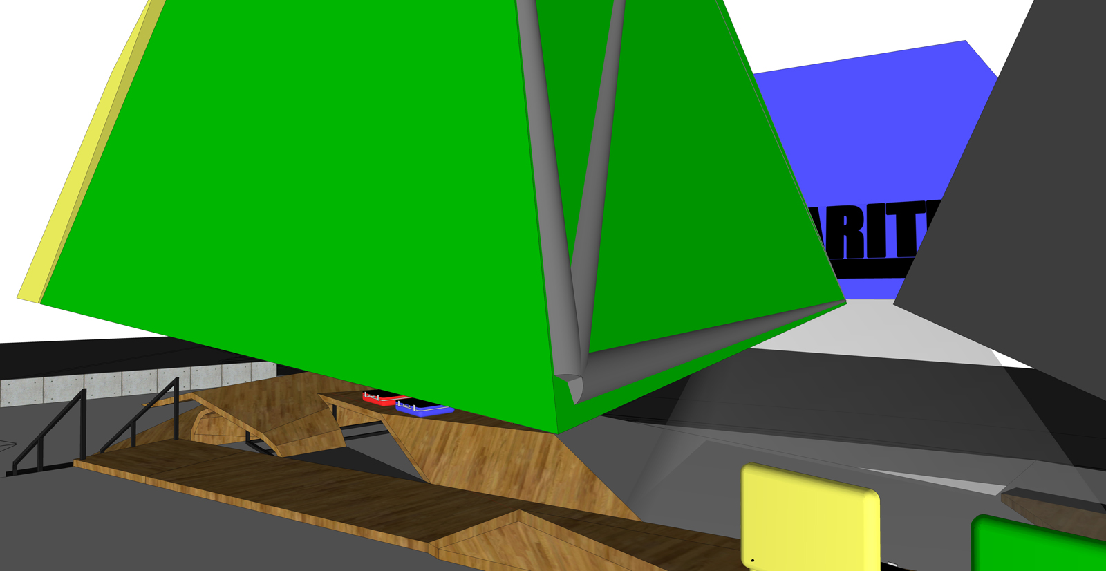
I tried your workflow, TIG, unfortunately there's something wrong either with the plug (shell) or with me
I followed step by step, but it's giving unexpected results:Althoug it's scaling proportionally, which is great, unfortunately it's not insetting by the same distance all the faces, giving weird results:
-
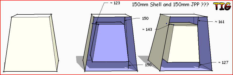
I've compared the Shell offset and JPP both at 150mm and they DO give inconsistent results!
-
Exactly TIG! so what do you think? is it just a bug or what? How unlucky am I?

-
Not so much a bug but a limitation of the tools' accuracy

SimpleShell is very simple it makes a copy of the object and scales it about its bounds.center to suit the entered amount... Therefore there will be cases where the 'offset' [inset?] is not th exact entered amount - that only applied if the face is perpendicular to one of the object's axes... -
well...I guess I'm gonna have to try a different approach to get the job done...I'll work on that the next days, I'll post the results.
If anyone else is listening and knows a possible suitable solution is welcome to share. -
I decided to try and make a true inset shell tool from scratch using a different method...
It sort of works but often falls over...
When it works we do get all faces inset consistently as specified.
I am trying to debug it - if I ever get it working I post it elsewhere on the forum and and link it back to here -
Awesome! thanks dude, can't wait!
-
After extensive testing I am sad to say that making a constant thickness 'shell' in code is all but impossible. The results I get are no better that scaling about a center [Jim's SimpleShell].
It is possible to combine a vertex's faces' normals to get a vector and make a new face matching the inset one BUT whilst it's easy to do for orthogonal forms other 'apexes' are awkward - you can easily get a 'good' vector for the first pair of faces, then the third face's normal has to be combined with that to make a 'combined' offset, which generates a new point that is then no longer constantly located from the first face[s], you readjust and repeat... disappearing up your own fundament! It IS theoretically possible... but the iterations needed are too much for me... -
Oh...I totaly understand TIG, and thanks in any case for taking the time to try and explain.
Hopefully google is listening and will include this feature natively in the next version.
Anyway in this case I have gotten to the result I was looking for, by using the 2D view to set the crossing points and once the paths were traced I used the procedure shownin the video.I'll stay tuned in case of news.
-
@tig said:
I've compared the Shell offset and JPP both at 150mm and they DO give inconsistent results![attachment=0:6uzo4tcl]<!-- ia0 -->Capture.PNG<!-- ia0 -->[/attachment:6uzo4tcl]
TIG, Wildchild,
Thanks very much for signaling this issue in JPP. When angles are really sharp, JPP does not respect the value of the offset.
As you may know there is no exact mathematical solution for the normal at a vertex in the general case, but I have slightly modified the algorithm to better respect the offset distance when you have a situation of polyhedron with large angles.
The fix is published in JointPushPull 1.6.
Fredo
-
Thanks Fredo - whilst it is still not [yet?] 'perfect'... it is greatly improved...
The iterations needed to get a vertex equidistant from a non-orthogonal set of vertex-faces just hurt my brain too much for me to resolve !
-
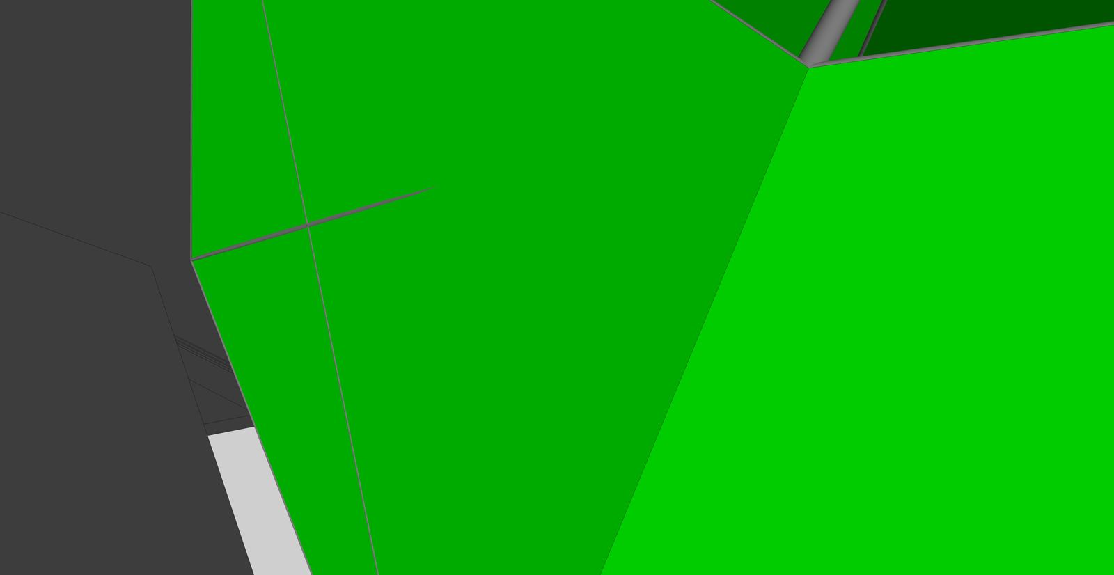
Thank you fredo for taking care of this! I've immediately tried JointPushPull 1.7 as soon as I could and here's the result:


Of course that is not a big deal, it's just about re-shaping the horizontal edges...but since we're here I pointed it out! Let us know if there's a way to fix it!Great job anyway fredo! Thanks!

Hello! It looks like you're interested in this conversation, but you don't have an account yet.
Getting fed up of having to scroll through the same posts each visit? When you register for an account, you'll always come back to exactly where you were before, and choose to be notified of new replies (either via email, or push notification). You'll also be able to save bookmarks and upvote posts to show your appreciation to other community members.
With your input, this post could be even better 💗
Register Login


Advertisement