Modeling issue: Cloth wrapped around a metal structure
-
Sorry guys I've been out of town for a while.
Thanks a lot for your precious suggestions (special shout out to TIG).
I tried your workflow, TIG, unfortunately there's something wrong either with the plug (shell) or with me
I followed step by step, but it's giving unexpected results:Althoug it's scaling proportionally, which is great, unfortunately it's not insetting by the same distance all the faces, giving weird results:
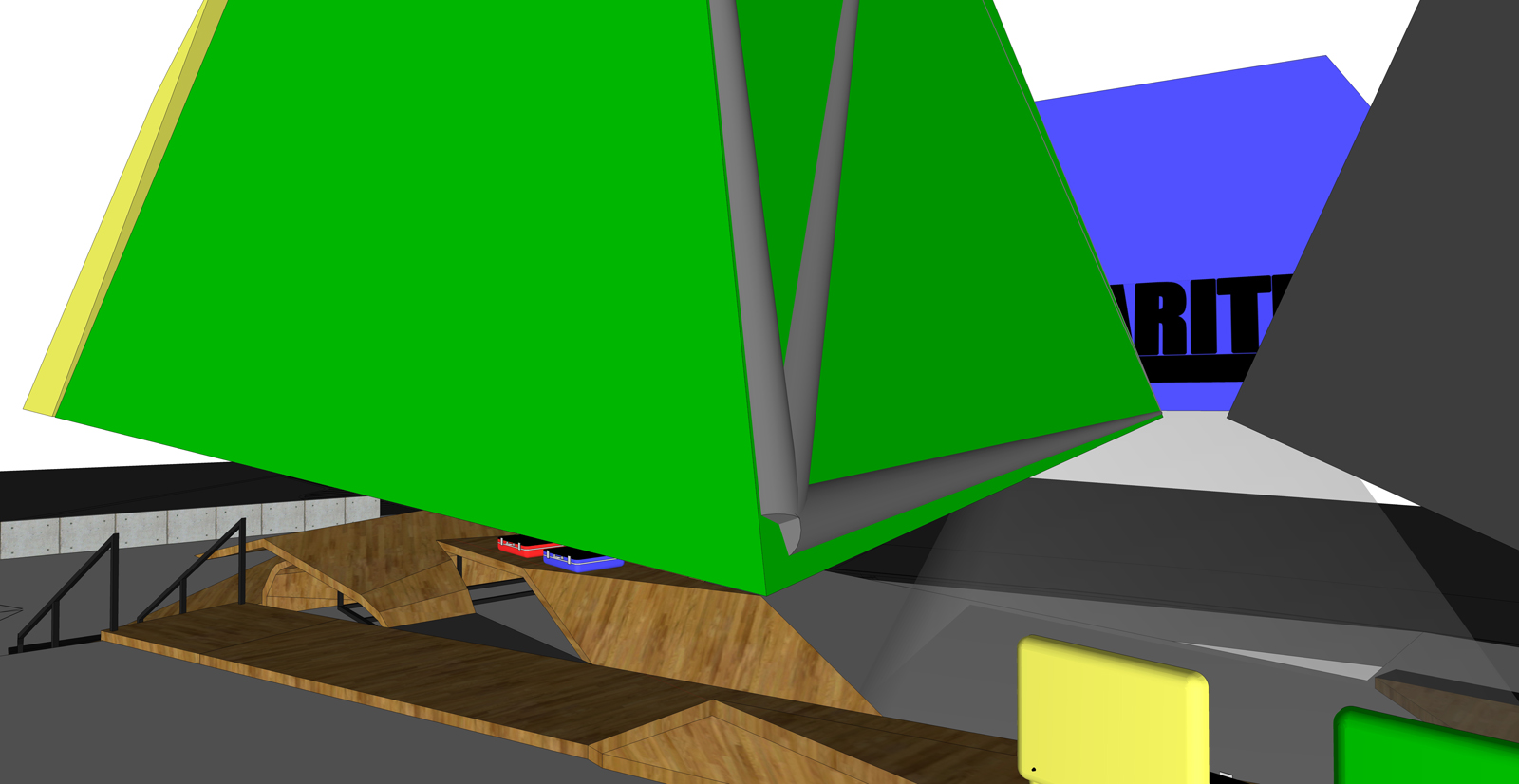
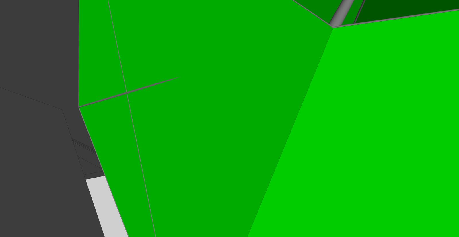
-
I've compared the Shell offset and JPP both at 150mm and they DO give inconsistent results!
-
Exactly TIG! so what do you think? is it just a bug or what? How unlucky am I?

-
Not so much a bug but a limitation of the tools' accuracy

SimpleShell is very simple it makes a copy of the object and scales it about its bounds.center to suit the entered amount... Therefore there will be cases where the 'offset' [inset?] is not th exact entered amount - that only applied if the face is perpendicular to one of the object's axes... -
well...I guess I'm gonna have to try a different approach to get the job done...I'll work on that the next days, I'll post the results.
If anyone else is listening and knows a possible suitable solution is welcome to share. -
I decided to try and make a true inset shell tool from scratch using a different method...
It sort of works but often falls over...
When it works we do get all faces inset consistently as specified.
I am trying to debug it - if I ever get it working I post it elsewhere on the forum and and link it back to here
-
Awesome! thanks dude, can't wait!
-
After extensive testing I am sad to say that making a constant thickness 'shell' in code is all but impossible. The results I get are no better that scaling about a center [Jim's SimpleShell].
It is possible to combine a vertex's faces' normals to get a vector and make a new face matching the inset one BUT whilst it's easy to do for orthogonal forms other 'apexes' are awkward - you can easily get a 'good' vector for the first pair of faces, then the third face's normal has to be combined with that to make a 'combined' offset, which generates a new point that is then no longer constantly located from the first face[s], you readjust and repeat... disappearing up your own fundament! It IS theoretically possible... but the iterations needed are too much for me...
-
Oh...I totaly understand TIG, and thanks in any case for taking the time to try and explain.
Hopefully google is listening and will include this feature natively in the next version.
Anyway in this case I have gotten to the result I was looking for, by using the 2D view to set the crossing points and once the paths were traced I used the procedure shownin the video.I'll stay tuned in case of news.
-
@tig said:
I've compared the Shell offset and JPP both at 150mm and they DO give inconsistent results![attachment=0:6uzo4tcl]<!-- ia0 -->Capture.PNG<!-- ia0 -->[/attachment:6uzo4tcl]
TIG, Wildchild,
Thanks very much for signaling this issue in JPP. When angles are really sharp, JPP does not respect the value of the offset.
As you may know there is no exact mathematical solution for the normal at a vertex in the general case, but I have slightly modified the algorithm to better respect the offset distance when you have a situation of polyhedron with large angles.
The fix is published in JointPushPull 1.6.
Fredo
-
Thanks Fredo - whilst it is still not [yet?] 'perfect'... it is greatly improved...
The iterations needed to get a vertex equidistant from a non-orthogonal set of vertex-faces just hurt my brain too much for me to resolve !
-
Thank you fredo for taking care of this! I've immediately tried JointPushPull 1.7 as soon as I could and here's the result:
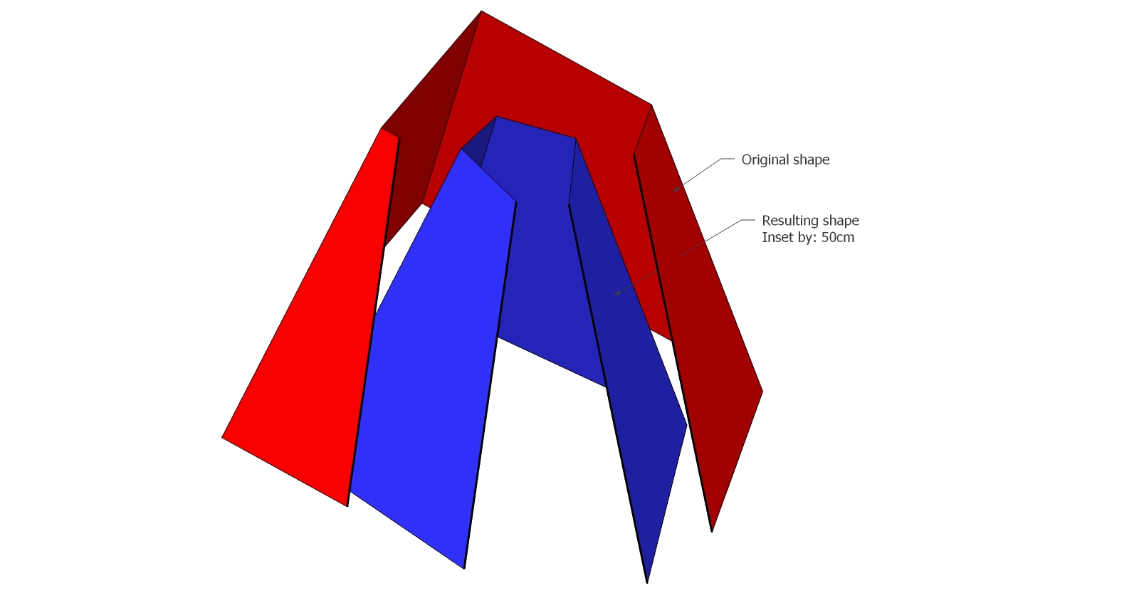
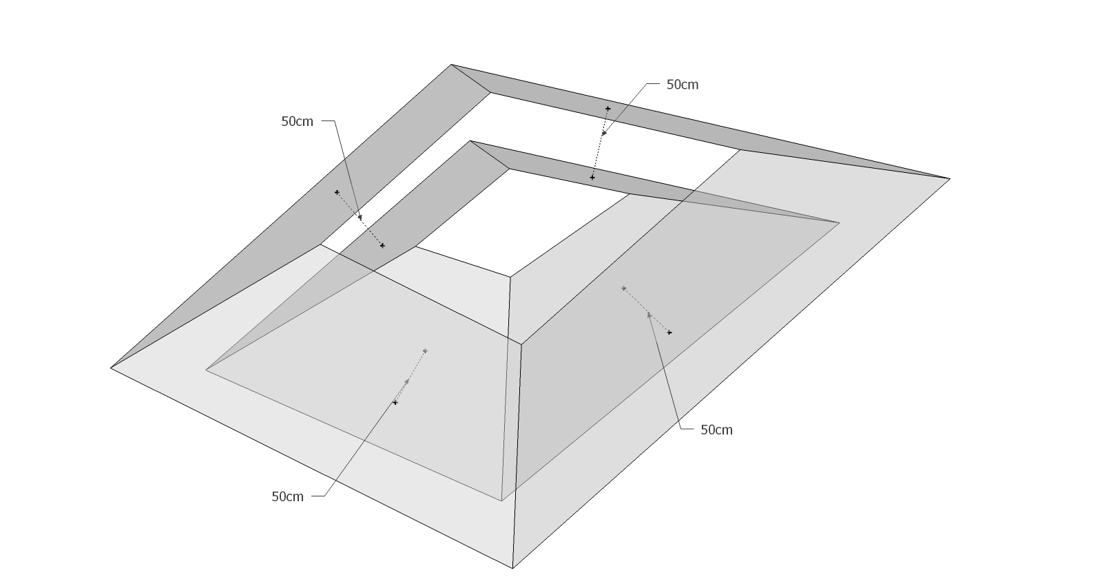
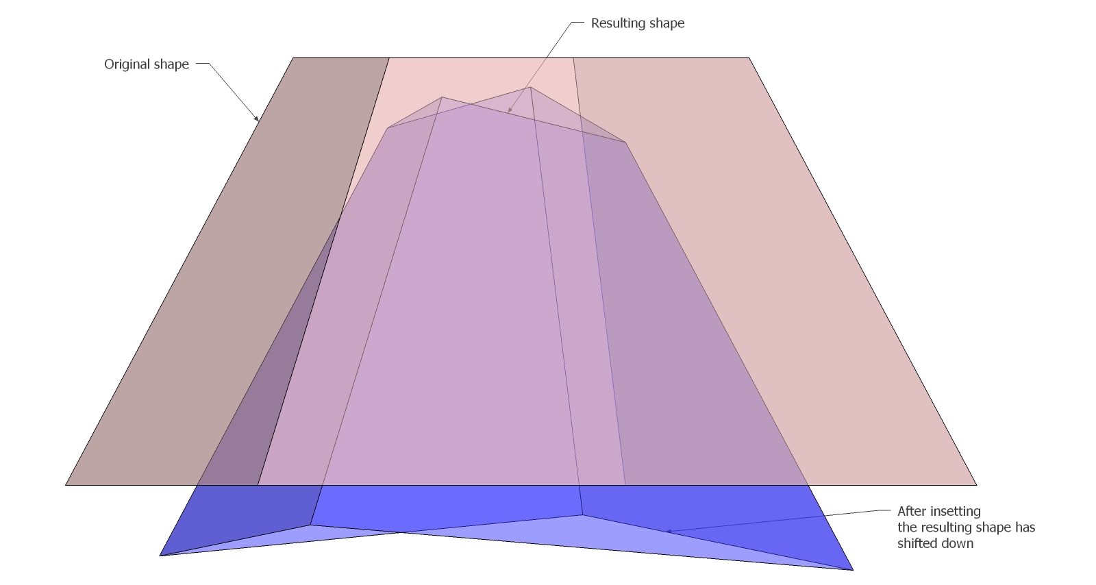
Of course that is not a big deal, it's just about re-shaping the horizontal edges...but since we're here I pointed it out! Let us know if there's a way to fix it!Great job anyway fredo! Thanks!
-
Wildchild,
For the top and bottom alignment, there is an option in JPP to guide a push pull along a plane.
In your case, if you pres CTRL + ArrowUp, you would force the Horizontal plane
Fredo
-
Dude...I don't want to bother more than I've done but
 , I tried this method and it actually does work, the top and bottom are now aligned, the thing is now the faces are not equally insetting anymore
  . Seems like that one excludes the other, as shown below:
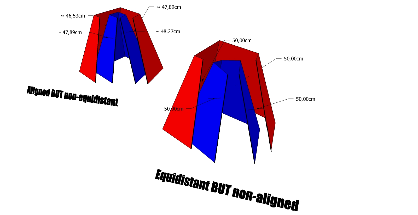
Most likely I am not doing it in the right way, in that case, would you be so kind to explain? Thanks
-
Could you please post your particular model above, because I don't obtain the discrepancy you mentioned. On my tests, the extruded faces are parallel to the original face and at the specified distance.
Thanks
Fredo
-
Sure enough I'm doing something wrong.
thanks
-
@wildchild said:
Sure enough I'm doing something wrong.
thanks
If you use the Tape tool to measure the corersponding edge, you will observe that they are strictly parallel at a distance of exactly 20cm. However, the orthogonal distance between faces is smaller.
I'll need to have a look and try to fix that if I can
Fredo
-
I know, I tried to mesure it! what shook me is that the top and bottom are equidistant while the orthogonal faces are not! And as far as i know this is geometrically impossible if the 2 faces are parallel (equidistant). The only solution to this would be that the inset face is not flat, or rather, made by non-coplanar triangles or quad-faces(but that's not the case). Does that even makes sense?
See what you can do! thank you.
-
you could use Smartpushpull plugin.
http://forums.sketchucation.com/viewtopic.php?f=323&t=23341&hilit=smartpushpullI applied it on each faces, then erase unwanted geometries about 5 mn work.
-
@gilles: DUDEEEEEEEEEE!! I say Bingo! it definately does work! how come I haven't noticed this plugin i don't know!
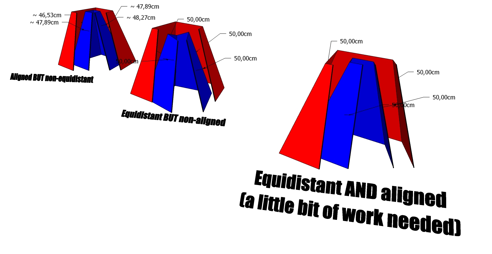
The funny thing is that in the 1001 pro bit tool bar which I have, there's a tool that behaves just like smartpushpull but can't handle small values, infact it wasn't working in this case.
It would be cool to just be able to interanct with the adjacent faces as well.
Advertisement


