Curve Based Upon Varying Given Heights
-
It seems you would want to specify xyz values for key points such as the transition point for sequential curves and key points for the curves' "attitudes",that is, maybe the xyz value of the midpoint of each curve. Obviously, you might also need to specify the xyz of the centerpoints of all the radii.
After all this precise input, you will probably still have to do some proportional/"eyeball" reshaping.
But then, maybe somebody already worked all of this out--in Sketchup--but I don't know that. -
@gaieus said:
Could you share this file? I am not promising anything just thinking.

You'll find it attached. I have no problem doing it the difficult way (with all of the precise input as mitcorb mentioned), but I've had such success with finding the appropriate plugin for difficult tasks I was hoping there would be one for something like this.
If there isn't, I may end up using Curve Shearing for each individual segment and see how that goes. Its not automatic, but its the easiest thing I can think of for the time being.
-
As outlined previously:
-
Hi thebreadking,
I believe Tgi3D SU Amorph has a very nice and easy solution to your problem. Please see the video below. I created the video in one shot, it is unedited, so a bit long (still only 3 mins 12 secs though).
Please note that you would not be able to do this easily with the free Training Edition as your curves exceed the limit of the max. number of vertices allowed in the free version. I have not tried it myself but you should be able to work around that by limiting the number of vertices in each curve to less than 10 and working with more curves.
[flash=480,390:1jivq7s2]http://www.youtube.com/v/XqHsDoiuYPY?fs=1&hl=en_US[/flash:1jivq7s2]
-
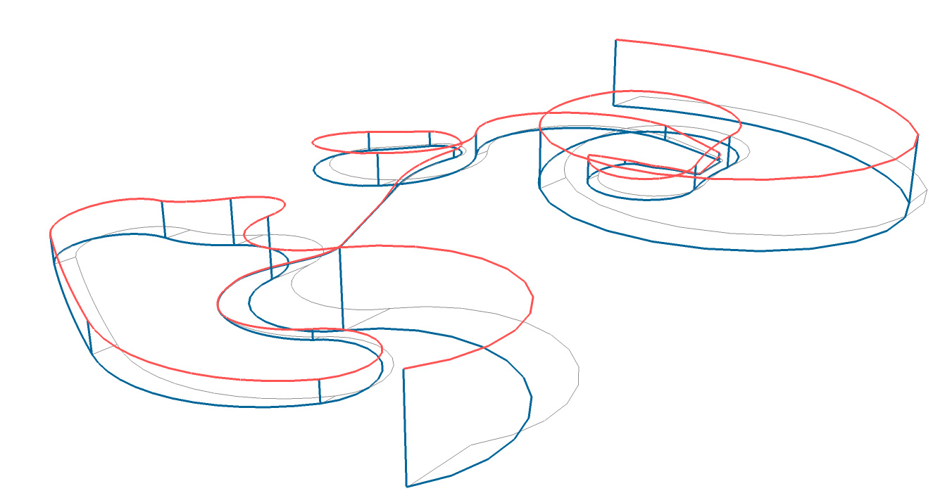
You could use Extrude Edges by Edges and Tools on Surface. First group all the vertical lines and weld the path into a single curve. The highest desired elevation appears to be at the start of the path; copy that vertical line to the end point. Group these lines. Extrude edges by edges using this group and the flat animation path you've drawn. Now use Line on Surface to connect the vertical points you've drawn. When the degree of curvature between the two points nears or is greater than 18 0degrees, you'll need to calculate the midpoint elevation and draw to that intermediate point before continuing on. The process isn't automated, but I think it will be easier than manually figuring all of the centerpoint elevations. Hopefully this makes sense; I can post something if it doesn't.
-
This is interesting as I was trying to explain to my son how Greek stone masons were able to perfectly replicate the entasis from one column to the next without having paper plans of computer files. At Didyma a stone was found with many varying length lines spaced every inch over the face of the stone. Nobody was sure what it meant until some one took those lines and spaced them the same distance apart as the length of the stone drums that make up a temple column. It turned out that the lines were the actual width measurement of the columns but the height of the drums on the stone were compressed from several feet to an an inch or two. The teams of workmen would all go to the same stone to reset their compasses as they worked ther way up the column. As a result not only were the columns practically seamless, butthey all matched to the thousanth of an inch even though hundred of workment were working the columns independently.
-
Didyma, what part of Arizona is that?-)
-
It is west of Honolulu. Turkey. I thin the measure rock was in a tunnel and archeologists missed the significance of thelines for years because of poor lighting. One day grazing light from the tunnel mouth hot the wall just right and researches had one of those aha! moments.
Didyma, Turkey. -
I knew it sounded familiar. I think my dad's friend Barry, took me there when I was a child:-)
-
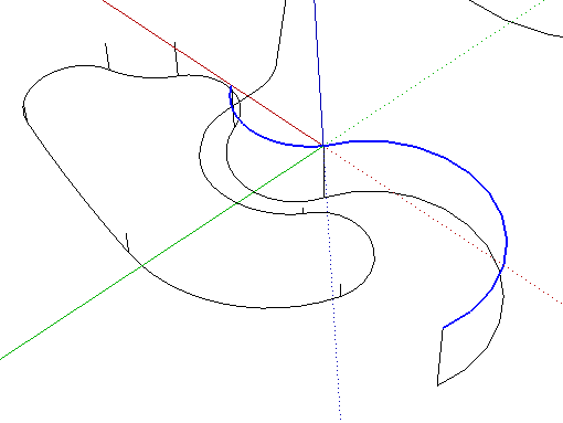
Does this work? The red is the path through the Z-values given. With more Z-values, the path would be smoother in its elevation changes.
-
The path defined is simply the midline. If this is for a roller coaster, you'd need a ribbon.
And the paths for the edges will need to vary to compensate for centripetal effects. -
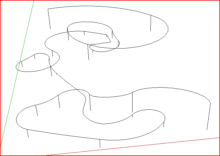
If you separate out the vertical lines and the curves by grouping the lines you can use the Move tool to adjust the ends of the curved parts to the tops of each line... They simply snap to them...
-
Your elevation ticks are way under sampled. There are many curves that can fit the data( plan view) you have presented. If you want just a picture then what Dave has shown is great but if its use is for some real world application then you will have to establish some criteria on the spacing of you elevation samples and usually based on some type of rms error etc.

Hello! It looks like you're interested in this conversation, but you don't have an account yet.
Getting fed up of having to scroll through the same posts each visit? When you register for an account, you'll always come back to exactly where you were before, and choose to be notified of new replies (either via email, or push notification). You'll also be able to save bookmarks and upvote posts to show your appreciation to other community members.
With your input, this post could be even better 💗
Register Login


Advertisement