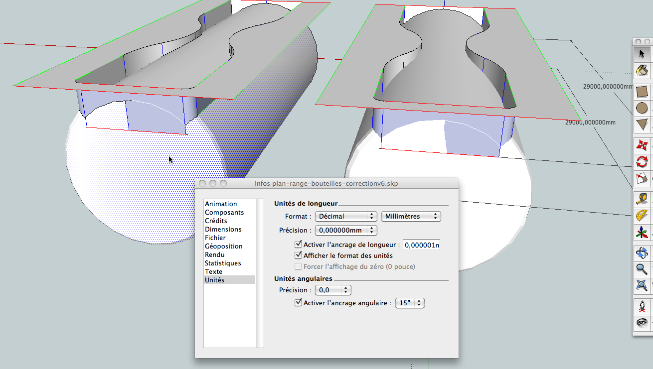
Sketchup is Inacurrate???
-
@unknownuser said:
(i'd honestly like to listen in on the two app's developers debating which one is 'right'
I have asked to Michael his position about that!

-
So! The Michael's answer!

@unknownuser said:
Hi Pilou, at a tangent discontinuity (the sharp corner point), what happens is the offset generated at each segment does not naturally match up, the natural offset of such a thing is this discontinuous set of segments like so:

@unknownuser said:
These offset segments are a constant distance away from the generator curves, like this:

@unknownuser said:
However, most people are not happy when their curves become separated like this, much of the time they would like for the offset to be one continuous curve.
So then the question becomes what to do in this area here:

@unknownuser said:
In MoI there is a "Corners" option to control the behavior for what to do to fill in this area between the natural offset pieces, you can set it to either Corners = Sharp or Corners = Round.

@unknownuser said:
If you are primarily concerned with getting "the most accurate offset", then I guess you would want to switch this option to Corners = Round - that will make that area filled in with an arc segment:

@unknownuser said:
That is the only kind of fill in shape that will result in equal distances at the closest point between the original curve and the generated curve. That's usually the strict definition of what it means to be an offset - "equal distance at every closest point". Here every line that you see between each curve is of the same length (within tolerance):

If you put anything other than an arc segment in the fill in area, it will not be a true offset anymore. However, often times people are more interested in maintaining the same general corner shape rather than having a strict "equal distance at every closest point" type result. That's what the other Corner = Sharp option is for, it works by extending the 2 shapes until they intersect one another. There are then different ways that it is possible to do the extension process. The way MoI will try to do it is it tries to extend the curve with curvature continuity (meaning for example an arc will extend as another arc piece rather than extending as a line) and if those G2 extensions meet up it uses that. If those do not meet up (it's possible for curvature continuous extensions to curl around and miss each other) it will try to do a line segment extension instead, that means though that the extension area is somewhat different in shape since a line is totally flat and devoid of curvature so the shape then has a curvature discontinuity with a little line piece in one area of it.
Anyway once you are talking about a sharp extension you have basically left the definition of the true offset behind at that point no matter which way you do it - the only way to maintain "equal distance at every closest point" is with the Corners = Round option with an arc being placed in the gap instead of any sharp piece.
So the "most accurate" offset I guess would either be something made up of 2 totally separate pieces with blank space between them, or with an arc between them.
@unknownuser said:
I have not yet looked at the thread that you are referencing yet, but often times when people argue about what the "most accurate" result it, there may have been a failure to actually define what the precise desired result actually is, like what it precisely means to be an offset. Also it's not unusual for someone to not actually want to get the "most accurate" result, they may be looking for something else like "most resembles original curve structure in corner points". If people have different actual goals in mind then it will be easy for them to disagree about how good a particular result is.
The Curvature continuous extension method can sometimes be a little odd in some cases, like the particular one you show there where it creates a fairly sharper angle than the original.
@unknownuser said:
I didn't really initially pick this behavior myself, it's just how the offset mechanism in the geometry works by default and I've left it that way since it seemed like often times it's a good way to do it.
Here are some other cases where you can see how it can be nice:


-
-
awesome seeing michael's opinion! I wish more devs would talk in that much detail on their apps behavior.
I think he raises some good points about user expectation vs 'true offset' as offsetting may not have a strict geometric definition (at least I've searched around for an actual definition in the course of this thread and couldn't find one )
)that said, I definitely don't think he'd find sketchup's solution acceptable as it doesn't return consistent distance even in the obvious (non corner) areas.
his last examples are good ones for backing up the way moi offsets.. especially the V example as I've built similar shaped walls and I cut the plates the same way as he's shown.
there are equally examples of how that method would be undesirable such as the example I posted earlier when the offset distance is enough to make the arc come back around and start forming a very sharp point. (and I didn't test last night as to what happens if I would of offset that even further.. I'm curious to get to a computer now to test it out
 )
)but I do think he's right that 'an actual strict definition' would be what you get with the round corner option because it give true offset value everywhere along the path. (rhino and illustrator both have those options as well but I left them out of the conversation.. but I now see those options as viable when talking about this stuff)
anyway.. thanks for asking him and @michael, thanks for answering him (though I honestly hope you didn't wade through thiese 30 pages to see me thanking you
 )
) -
@wo3dan said:
@driven said:
@wo3dan said:
Yours is for “nice looking”, not for having accurate predictable measures across, along the segmented arc.
The 'accurate predictable measure' in this example is [r1 to r2] = 1000mm, how more accurate can you get?It can be measured at the shared central 'cardinal' axis on equally segmented arcs.
For an uneven number of segments [r1 - r2] still equals 1000mm.
sorry this is accurate[quote @Jeff (mathematically).. ], any other way is for 'the look'.
Well John, you can't. I'll have to admit that. I was focussing to much on keeping the segments endpoints to where to be convenient (still on a correct true arc location). But any "repair" solution at the end of the child arc (=offset) would then be matematically incorrect. The chord isn't covering the correct angle and not in the exact location.
If I were to choose between a variety of true arc offset solutions in SU, it would be yours. The endpoints may not be located conveniently, but they are on the correct true arc, start to finish! Local measuring may require some tweaking in the number of segments in the child arc. But that doesn't change the true arc('s position)

I think I may have missed an example model along the way so can you permalink me to the post which contains this solution you're talking about ? johns example which I remember didn't have any accurate arc points

fwiw, chord length between segments doesn't have anything to do with accuracy of an arc. and I can show you a few examples where you'll need oddball segment length which varies over the course of an arc.. what matters is that the vertices (no matter how they're spaced) remain a true radial distance from the cpoint.
-
hey Jeff,
can you see any inaccuracy with my effort, it looks better with more sides, but you can still change those...
removed the image showing that the cardinal point still worked when extruded, as I think it caused confusion, try it with the .skp above
john -
@unknownuser said:
I think I may have missed an example model along the way so can you permalink me to the post which contains this solution you're talking about ? johns example which I remember didn't have any accurate arc points :?
http://sketchucation.com/forums/viewtopic.php?f=15&t=44142&start=420#p452970
Hi Jeff, it is the one you slagged off...
john
-
@gilles said:
Try to intersect those geometries correctly.
yeah.. i've seen the 'color by axis' problem before and i think it's just a matter of the tolerance being used as to when to color&display a line as 'on axis'
but that model is off:
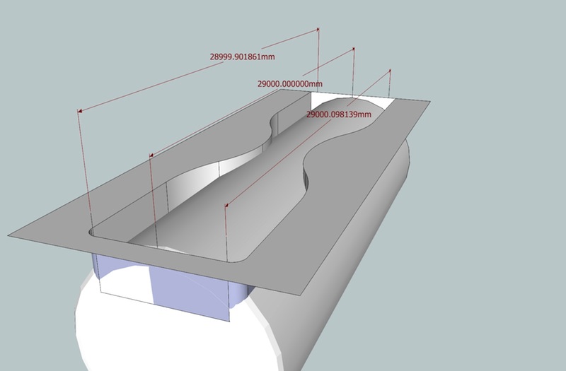
-
@driven said:
@unknownuser said:
I think I may have missed an example model along the way so can you permalink me to the post which contains this solution you're talking about ? johns example which I remember didn't have any accurate arc points

http://sketchucation.com/forums/viewtopic.php?f=15&t=44142&start=420#p452970
Hi Jeff, it is the one you slagged off...
john
ha.. i hope my slagging isn't coming across in an offensive manner.
 (it probably is but i really don't mean it like that)..
thing is, you have the arc dimensioned as R1.5m, which it is.. except - it's not sharing the same centerpoint as the R2.5 arc which it definitely should be doing..
-
So is this my inaccuratie or SU?
You can tell me.
-
@gilles said:
So is this my inaccuratie or SU?
You can tell me.
sketchup is inaccurately giving you feedback that your model is accurate

but switch off the whole 'color by axis' thing then get in there and measure and you'll see the model is actually skewed..
[edit]
thankfully, the su devs have a much tighter tolerance set for their inference engine.. if they used the same tolerance for drawing as they did for 'color by axis' then we'd be in a world of hurt!
-
Color by Axis is often incorrect. I've had many models where two models where coloured to be on the same axis, like a wall where I've been unable to cut a hole with PushPull because the faces made from these apparently parallel lines where not parallel after all.
-
@unknownuser said:
sketchup is inaccurately giving you feedback that your model is accurate
That's the point, if draw something I want to know it is good or not, not a "looks good".

-
@gilles said:
@unknownuser said:
sketchup is inaccurately giving you feedback that your model is accurate
That's the point, if draw something I want to know it is good or not, not a "looks good".

yeah.. i hear what you're saying.
in the case of 'color by axis', i tried using that as a troubleshooting measure once a long time ago and found it to be useless regarding accuracy.. so i never used it again

sort of along the same lines but something i really like about rhino..
it lets you adjust the tolerance of the app itself.. granted, it can be really confusing at first and you don't really know how you should set it up until you learn the way the app works but after that phase, it's sweet..say i have my tolerance set to 1/1000th inch.. i now know everything in the model will be at least that accurate.. but what's really good about it is that suppose i try to do an operation which will not be possible within my tolerance..
rhino will tell me "look, if you want to join those surfaces, we're going to have to double your tolerance.. is that ok?"so i can now say "yes.. go ahead" and i'll know my tolerance for that given portion is within 1/500th inch..
where as on sketchup, it won't tell me that.. it just proceeds to fill in any old thing and although i know there's an error, i don't know how much.. but if it could tell me "hey, your arc is off by 1/500th inch here" then at least i know that falls well within what i require for accuracy in which case i would OK the operation..
but it gets back to midway in the thread about tolerances.. sure, a micro error is no big deal in real world but i can make sketchup give a huge error as well.. so having no feedback on the size of the error makes me automatically assume it's the worst possible error..
-
....then you try and use the Query Tool to identify the vert that is causing the problem to be told it is x/y/~0
...you try and fix the ~0 vert but you can't because SU's dislike of small measurements doesn't allow you to fix the error it introduced in the first place.
....fix model doesn't work, make planar doesn't capture it. drape doesn't fix it and so on....
....i suppose it is exaggerating the obvious and making the essential unclear
-
I've been playing with an idea of a cleanup function that will readjust vertices to be perfectly aligned - something that might be able to recover models that act badly, like some DWG imports.
-
@unknownuser said:
ha.. i hope my slagging isn't coming across in an offensive manner.
 (it probably is but i really don't mean it like that)..
I'm thicker skinned than that even if it was malicious!!!
@unknownuser said:thing is, you have the arc dimensioned as R1.5m, which it is.. except - it's not sharing the same centerpoint as the R2.5 arc which it definitely should be doing..
where are you seeing this second centre point, I only used the one from the original drawing?
as I said later, I think the 2nd Radius is out by 0.004685mm and SU is correcting that.
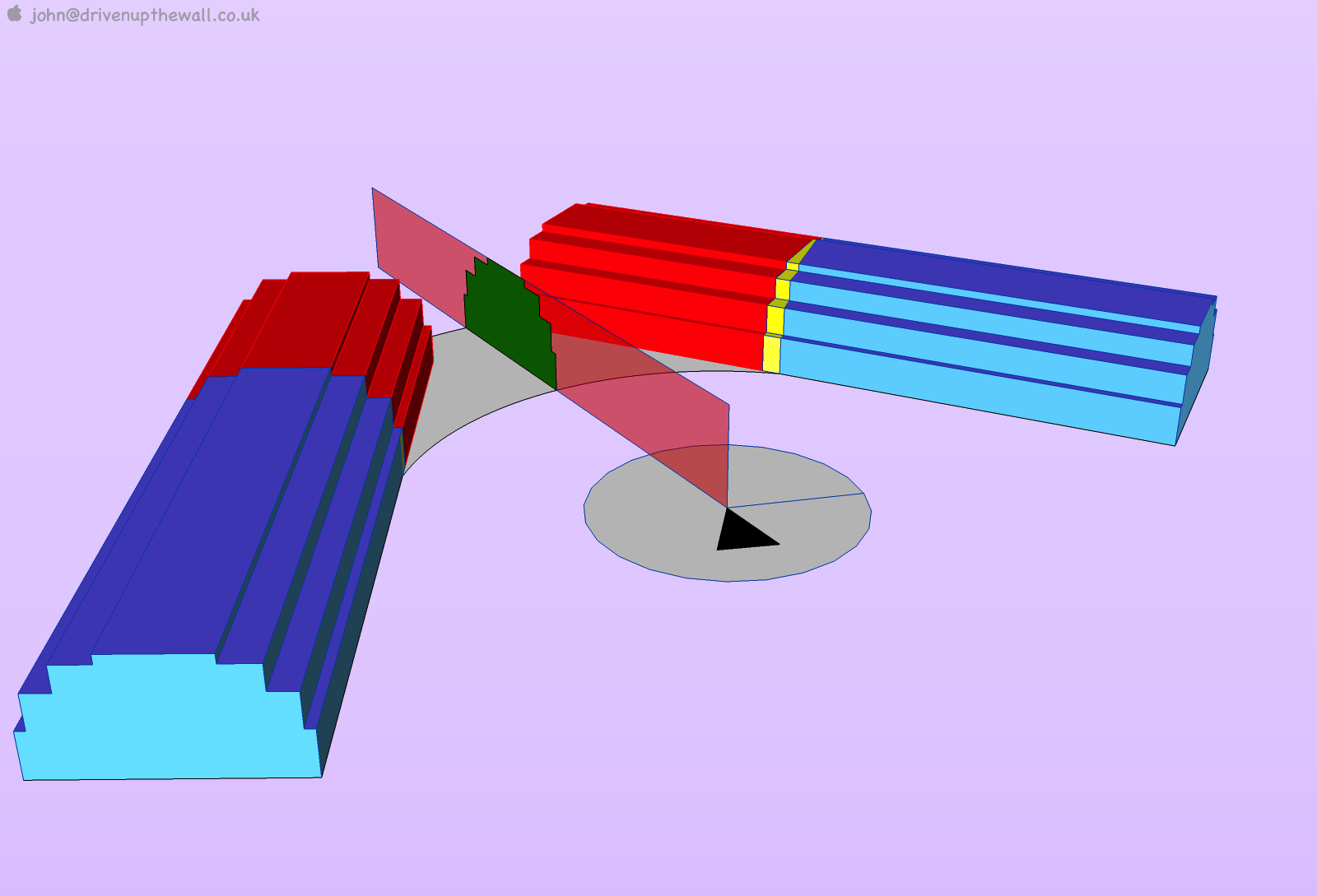
click on profile group and rotate until the line becomes dashed... BTW it only has 1 central axis axis/axlejohn
-
@driven said:
where are you seeing this second centre point, I only used the one from the original drawing?
as I said later, I think the 2nd Radius is out by 0.004685mm and SU is correcting that.john
if you start a line on the tip of the arrow you have drawn then go out to each of the larger arc's vertices, you'll see that you consistently get 2500mm as the length..
if you do that same thing to the inner arc, you'll see that the length varies (and it's never exactly 1500)..
-now-..
delete the arrow you have as the centerpoint.. establish a new centerpoint using the inner arc as reference.. then repeat what i described above.. the inner arc will now consistently measure 1500 to it's vertices whereas the outer arc gives a variety of lengths..ie- they aren't sharing the same centerpoint.
[edit]
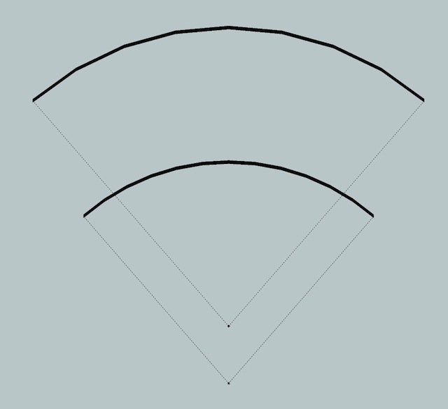
an exaggerated (ie-more easy to see with our eyes) version of what's happening looks something like this..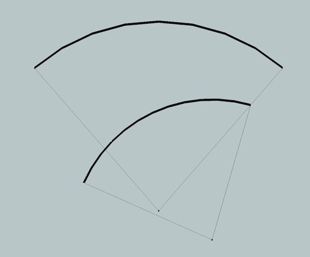
or maybe something like this.. (i haven't got in there to really figure out how it's off.. i just know they're off
 )
)
-
@unknownuser said:
ie- they aren't sharing the same centerpoint.
the error was in the radius, which I had mentioned, possibly due to it being a quick lash up.
anyway I think the ~0.005 error is now corrected...
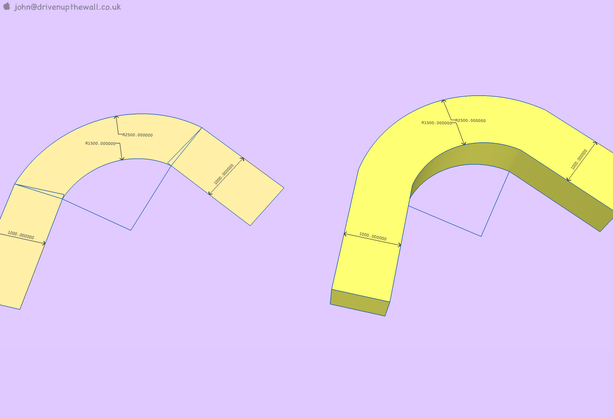 2Arcs_36sided.skp
 -
@driven said:
@unknownuser said:
ie- they aren't sharing the same centerpoint.
the error was in the radius, which I had mentioned, possibly due to it being a quick lash up.
anyway I think the ~0.005 error is now corrected..
getting closer ..now you have to deal with those pesky edges not being parallel..
 (they're not consistently 1000mm apart)
i'm saying though.. this situation is nearly impossible to draw/offset accurately in sketchup.. i'll attach the correct version and i'll also leave the method i used to obtain them in the model (hint- dynamic components running pythagorean theorem calculations on both sides)
that's the only way i can figure out how to do this accurately without leaving sketchup.. but i also feel sketchup could be smarter and do the maths for us

Advertisement
