Roof Models
-
Hi Tony and welcome!
Not from an architect's view but merely from SketchUp: yes, something like that.
- Model the pieces on Layer 0 (let's not call them "components" at this time yet).
- When done with a rafter or something, select all its geometry and no, do not make a group but a component (nowcomes the term). Anything that will have more than one instance in the model should be a componentrather than a group.
- Now "move" your component to any other layer than Layer 0 (note that the raw/primitive/loose - whatever you call it - geometry inside the component is - and should be - still on Layer 0)
-
@gaieus said:
Hi Tony and welcome!
Not from an architect's view but merely from SketchUp: yes, something like that.
- Model the pieces on Layer 0 (let's not call them "components" at this time yet).
- When done with a rafter or something, select all its geometry and no, do not make a group but a component (nowcomes the term). Anything that will have more than one instance in the model should be a componentrather than a group.
- Now "move" your component to any other layer than Layer 0 (note that the raw/primitive/loose - whatever you call it - geometry inside the component is - and should be - still on Layer 0)
Hi Gaieus,
Thanks for your quick response. Now that I have the Layers problem solved heres another question.
Why Do I Make 'Components' instead than 'Groups'? My models can have as many as thirty individual parts.Thanks
Tony -
There are a couple of advantages of components over groups (the list may not be concise - others are welcome to chime in to add to it)
-
when there are more than one instances of the same component definition in the model,
-
SU will only need to keep the definition (geometry set and inside materials) of one "in mind" and only the position, size, material, alignment, location etc. of the others.
-
when you change the definition (say by editing one instance), all the instances of this same definition will immediately change
-
You can always easily change the axis of a component (thus changing its insertion point or gluing/cutting plane though with rafters, this latter one is irrelevant)
-
you can save components for further use and form your component browser, you can easily insert any component into your model
-
you can save and reload components, swap one component definition with another component definition etc...
So given that in a roof model, there are generally lots of similar pieces, there is a big advantage to use components instead of groups.
Otherwise groups are very similar to components - they can even have instances of the same definition - the only problem is that you cannot access these features from the modelling interface (and changing one instance of the definition will make it automatically unique)
-
-
Understood, but if I am modelling a hipped roof. I will need to edit the parts as I assemble the roof. I need plumb cuts at ridge level and seat cuts at wallplate level. Do I assemble the entire roof in Layer 0, make all my rafter cuts and THEN move them to their individual layers?
-
Layers don't separate entities so forget that from you ACAD training. They only control visibility.
As Csaba said, you make components of the parts that go into making the roof. And when you want to make the plumb and seat cuts, you can open one of them to edit it and all the related instances will get the same cuts. If you have some instances that need different treatment--cuts are in different places, select them, right click and choose Make Unique. This will break their relationship to the others. If you have more than one instance of the component selected when you use Make Unique, those instances will remain related. This is very powerful for something like what you are working on.
Once you have all your components set up on Layer 0, you can assign the components to other layers. So you might have a layer for the walls (whatever you show of them) and another for the rafters and a third for the sheathing. Depending upon what you need to show the students, you might have trusses that are broken down into different layers so you can control which elements of the trusses are visible. So you might have a layer for the collar ties and another for the nailing plates and so on.
For my work flow I prefer to get all of the parts drawn before making the layers and the layer associations. You don't have to do that but I find it easier for me. After all the parts are drawn I make the layers. Then I turn off their visibility and begin making layer associations by selecting components and changing their layer assignments in Entity Info. I know I've got all the components assigned to layers other than Layer 0 when I have a blank drawing window.
Make sure that the lines and faces in each component remain on Layer 0. And don't change the radio button away from Layer 0.
Here's an example showing how I divided the model into layers. You can see the rafters which are selected in the screen shot are all instances of the same component and they are associated with the layer called "Trusses". Of course the collar ties and in this case the nailing plates are also on the Trusses layer. I put the hurricane clips on their own layer, though, because I had need of showing them separately in the plan.

Click on the photo and you can get to a larger view of it. -
DaveR, a comprehensive and informative response, thanks for that. Just to clarify - the actual editing process of my components is done in Layer0 also?
Thanks for your input, it is appreciated.
-
Thank you.
You'll just open the component for editing (double click on it with the Select tool or right click and choose edit Component) and make the required changes. Just remember to leave Layer 0 as the active layer (radio button to left of the layer name) or the stuff you draw while editing the component will end up on some other layer. That's a quick way to ball up your model and make bad words come out of your mouth.

Again, layers only control visibility in SketchUp. You'll only make changes to layer associations for components (or groups if you use them; I don't) and when you un-check the visibility box for a layer it is like the Romulans turning on their "cloaking device" to hide their Bird of Prey.
-
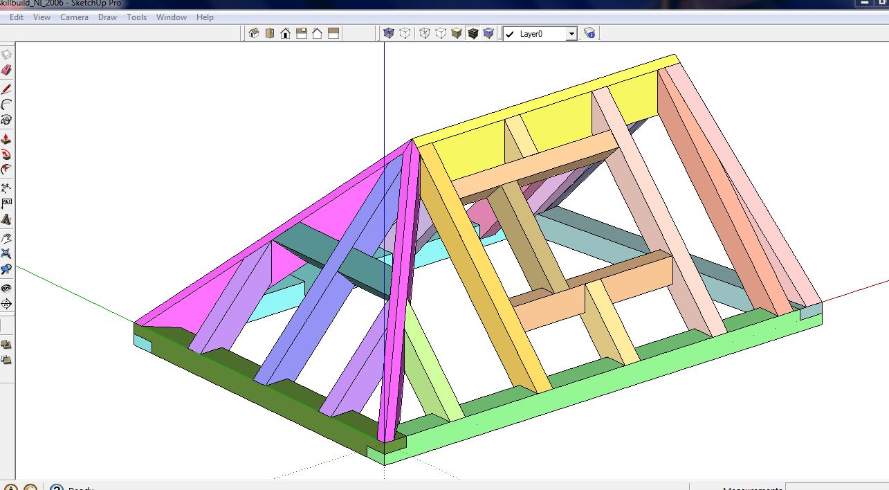
Tonight, I started working on a model using the techniques that this forum have passed on to me.
It is progressing well and solved a lot of problems that I encountered in the past with layers and associated geometry. I'm grateful of the support I received!!
These models are used to coach young Carpenters for National Skills competitions - note the inclined rafters!
Next week two of my apprentices compete in the UK Finals for GOLD!Update: Here's the finished model!
-
Are there any nice wood grain materials I can add to the current library of materials?
The default materials are not very good. -
There are some OK materials out there. Take a look here: http://www.arroway.de/en/index.html for example. Don't use hi res images. Those aren't needed and will just bloat the file.
The roof looks good.
-
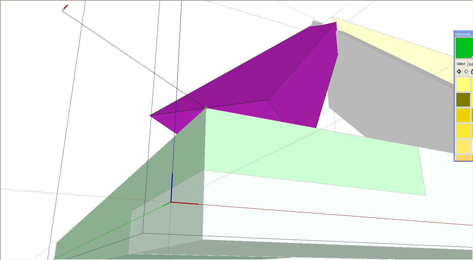
Many of the routines that I have explored in SU are quite easy to grasp. Modelling the roof model I posted was quite easy. However, one area that was a pain was forming the bevels on the hip rafters.
What I done was draw a thin slab that I made into a group. The slab was then moving into position at the same pitch as my roof and the hip rafters were subtracted from it to remove the bevels. Quite easy but I am sure the experts here can come up with a quicker way of doing it! -
Well, that's one way to do it. I can think of other ways, too. First, the hip rafters would be instances of the same component so only one would need to be edited. all the others would be components as well. Second, I wouldn't have chosen to use Solid Tools because they would convert my components to groups and create extra work..
One option I might use is to start with the hip rafter in place. With the ridge and wall top plate pieces in contact, you can see where the ends of the bevels would be. Just open the hip rafter component for editing and draw lines along the sides of the rafter from point to point and a line along the center line of the edge (for the peak of the two bevels) and delete the bits you don't need.
-
DaveR,
I think I prefer my way, I tried using your method in the pastbut its less accurate.
I have modelled another roof structure and this time I need to mirror the layboard that
rests at the back of alley, the dormer to form the valley. I want one in the valley, hidden from
view. In autoCad this is achieved with a simple 'mirror' operation.How does that damn 'flip' tool work?

-
The Flip tool works on RGB/XYZ axes.
There's also my olde 'Mirror' tool that lets you mirror a selected about any picked 1/2/3 points... and also to keep/erase the original object[s] - much more like CAD...
Search in the Plugins Index to get it... -
Tony, I don't know how my method could be less accurate but you can draw it any way you like.
As to the Flip tool, TIG has given you the basics. If you haven't rotated a component and the component's axes are aligned to the global axes, you can use the global axes for reference when flipping. If you wanted to copy and flip the entire half of the roof to the other side of the ridge, copy it with the Move tool and then, while all those components are selected, right click on them and choose Flip>Along Green Direction.
-
@tig said:
The Flip tool works on RGB/XYZ axes.
There's also my olde 'Mirror' tool that lets you mirror a selected about any picked 1/2/3 points... and also to keep/erase the original object[s] - much more like CAD...
Search in the Plugins Index to get it...Tig, thanks for your advice and 'mirror' tool. I'll have a look at the plug-ins because I believe
the 'unfold' tool is also useful. -
@dave r said:
Tony, I don't know how my method could be less accurate but you can draw it any way you like.
As to the Flip tool, TIG has given you the basics. If you haven't rotated a component and the component's axes are aligned to the global axes, you can use the global axes for reference when flipping. If you wanted to copy and flip the entire half of the roof to the other side of the ridge, copy it with the Move tool and then, while all those components are selected, right click on them and choose Flip>Along Green Direction.
Sorry DaveR - less accurate was probably not the correct choice of words. I don't like the idea of
having to redraw faces that were previously grouped. I have terrible memories of my first days using
sketchup and trying to bevel things this way! You replies are always welcome! -
Could you explain "having to redraw faces that were previously grouped?" I don't understand what you mean by that.
-
@dave r said:
Could you explain "having to redraw faces that were previously grouped?" I don't understand what you mean by that.
When I drew the bevels using the line tool I then deleted the faces to form the bevels. I then had to redraw that face which was a pain.
-
If you draw all the edges of the bevel, the face should fill in automatically. Still, there are various approaches to most things. Draw it as you wish. You could draw a profile of the waste side of the bevel and use Push/Pull although the profile must be perpendicular to the path of the bevel and with the pieces you're drawing, you have to do some clean up at the ends.
Hello! It looks like you're interested in this conversation, but you don't have an account yet.
Getting fed up of having to scroll through the same posts each visit? When you register for an account, you'll always come back to exactly where you were before, and choose to be notified of new replies (either via email, or push notification). You'll also be able to save bookmarks and upvote posts to show your appreciation to other community members.
With your input, this post could be even better 💗
Register Login


Advertisement