Sketchup and production drawings.
-
Since I am old school, I subscribe to the convention of using scalable orthographically projected images for use in production drawings. However I have read a lot of "alternate points of view" regarding the use of 2d drawings of 3d view for the use in production plans. My knee jerk reaction is, NO!; while I can make arguments to support my beliefs, that doesn't advance the use of 3d modeling as a useful tool in regards to construction documents. So lets see if we can have a discussion regarding that subject, to advance the "state of art" in a meaningful manner.
I believe the issue at hand is "on one hand", is the ability to visualize 3d views on 2d media in a meaningful way that includes scaling by hand, that drawing, and "on the other" better visualization of that view. I suppose the question is, do the drawings have to be scalable by hand? If not, how should the project's scale be presented?
-
have a look at dennis fukai's blog. he has a very interesting point of view on this. he is the author of several books in which he shows a revolutionary way to use sketchupi não the production of construction docs.
-
These days most good construction drawings have a '...do not scale - measure from site or use figured dimensions only - if in doubt ask...' etc disclaimer in the notes column. As it is so easy to copy drawings these days 'scaling' from a drawing to build from is a recipe for disaster... Remember that "if you haven't designed it someone on site will" - if you're happy for the carpenter on site to design a minor unseen detail that's fine... but the important stuff should be clearly explained in your documentation to those about to do the work - expecting someone to 'scale off a drawing' and hope it'll be OK is abdicating responsibility...
So construction documents should describe in writing what can be readily described by drawing, describe in drawings what can't be readily described in writing - and use the most appropriate techniques to explain clearly what is needed - this can be 2D or 3D illustrations.
2D general arrangement drawings are still usually produced at commonly expected scales, with useful dimensions written on them - that way everyone in the building process gets the info they have come to expect in '2D'.
BUT whilst Plans/Sections/Elevations etc in 2D can be a tried and useful way of finding out how something is sized or what goes where in a building, it can often be more useful to give the guys building it some 3D representations of aspects of the design - this can avoid ambiguity and misinterpretation, and clearly can help explain how complex detailing in built up in a way 2D cannot - helping the managers understand who does what when etc, and the guys putting it together see where they are heading too...
Use the most appropriate means that the ends require...
So 2D + 3D is the best way to realize a building with minimal hassle...
-
I suspect the disclaimer, similar to the one I use,-) is more for "covering my ass" then anything else. When you think about it, Cad should result in more accurate scalable drawings, making hand scaling more reasonable.
One problem with 2d drawings, is visualizing forms going around the corner. Axonometric drawings deal this, but have not had much acceptance in the construction industry. I wounder why that is? But as a solution, if the amount of paper is not a problem, how about the following, say for interior elevations:
Between each noted, dimensioned, orthographic view, is a perspective of the pair of views. Problem here (to my knowledge) is that there is no app. that effectively permits changes in the orthographic view to be automatically reflected in the 3d view, and for changes in the 3d view to automatically revise the noted, orthographic views.
It is possible to do the italicised part above, but it remains difficult to automatically update the position of notes, and all dimensions when changes are made to the model.
I am familiar with Fukai's work, but have not seen anything that works for me.
-
Surely the real issue is that we shouldn't be even be thinking of producing printed material?
Everyone ought to be able to use a system like SU to examine a good, detailed, model of the project and work from that. With devices like iPad etc it should be the standard to have them at the site and to work from up to date soft design models. Your foundation corners and datum points ought to be drawn on the ground by laser from a fly-over of a Predator drone

If one does really need to fall back on dried slivers of dead tree then surely SU/LO can do an adequate job of keeping the various views up to date? I haven't had any issues in my project with that. Yes, there is a problem if design changes require big changes in notes attached to a view. What would be wanted to automatically handle that (aside from a real, practical, helpful AI) ? You might be able to implement a way to attach notes to the parts within SU and 'pull them out' in LO. Then a deleted part would automatically remove the unwanted note, for example.
-
I agree with TIG;
From a different engineering view.
You think CAD is more accurate but what about all the other errors of getting the line laid down on paper and the paper variation itself and the accuracy of the person doing the scaling and the errors in possible multiple prints?? In my 34 1/2 years of Aerospace engineering I have approved 100's of drawings and cannot remember one time I relayed on scaling of a drawing or accepted that in the shop. If manufacturing needed some missing info there was a formal system set up to get that question answered by engineering and if necessary this was followed up by a new drawing release. If I had a question setting down with the designer on the drafting board ( yes I am old)or on the computer was the way go. Over the years we progressed from drawings on Mylar to totally paper less system but the drawing release still follows a basic approach of initial PDR level, then CDR level then final build release. During those phases material and process, manufacturing engineers and manufacturing review the drawings to make sure the item could be built ( Or new processes , machines etc would be developed / bought), stress / dynamics, thermal, QC, procurement , test, customer+ their consultants, our worst case analysis, reliability etc. would also get in on the sign off. 3d drawings are useful for assembly level but I question that across the board just because of the complexity to create them. How would you like to make a 3d drawing of a PCB board and where would you get the info. on the potentially 100's of parts required to do that. Yes manufacturing needs that for pick and place but given the lead time on parts ( some times a year or more) the final config. may not be what you draw so now you have QC rejection to deal with and a redo on your drawings. Or you have a separate generic library , two to support??
The point is don't assume 3d is the way to go until you understand all the problems. For your engineering use it maybe
-
@honoluludesktop said:
Between each noted, dimensioned, orthographic view, is a perspective of the pair of views. Problem here (to my knowledge) is that there is no app. that effectively permits changes in the orthographic view to be automatically reflected in the 3d view, and for changes in the 3d view to automatically revise the noted, orthographic views.
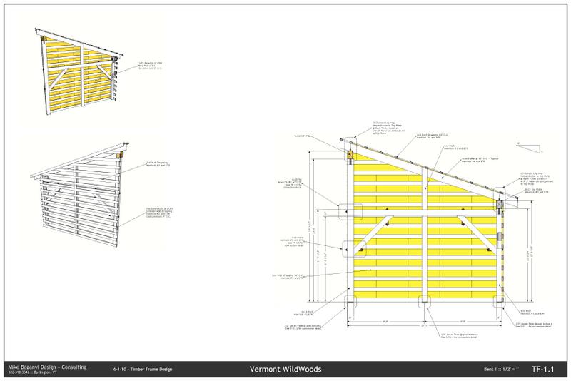
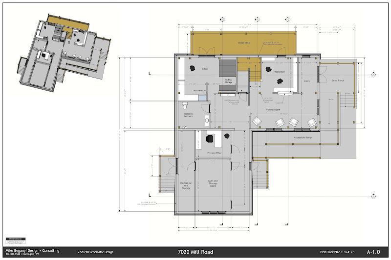
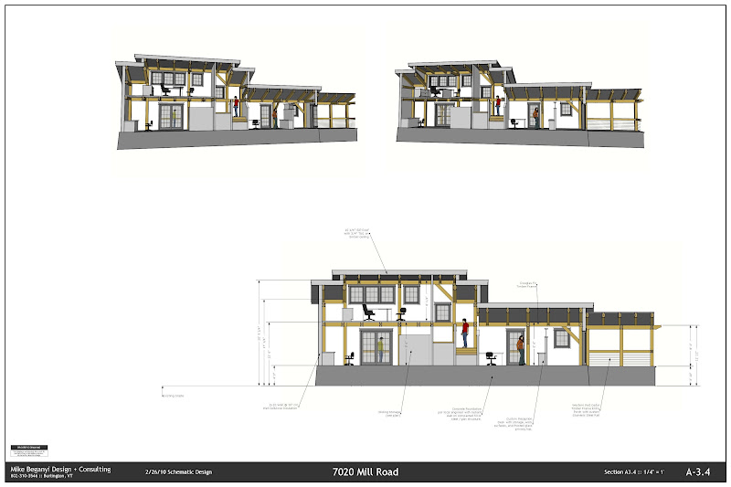
Its not automated yet, but I usually include details or 3d views of the building with the elevations or floor plans when I get to use LayOut and SketchUp on a project... the dimensions and notes certainly won't automatically update... but compared to some Revit drawings I've seen - this is much clearer - and you don't have to reinvent your whole process to fit into a particular CAD package...
-
I don't disagree with any of you, I'm just asking how could it be done? In a way to accommodate the $100,000,000.00 building as well as a $300,000.00 remodel. The value of a scaled drawing isn't getting dimensions, but in scale. If you spend some time in the field, in environment of pouring concrete, excavating rock and soil, masonry, and hot steel, you begin to appreciate the value of paper drawings.
Its not enough to say it should be done, but to demonstrate how to do it. Contractors in my experience, are the last to embrace a new building technology.
bmike, your drawings are great, but they are still not production drawings. At least not in the manner that I am accustomed to seeing.
-
I think that bmike's examples are good ones showing a mix of 2D and 3D that work together to help the user.
Construction information is a means of communicating ideas and details to many other people - they don't all want or need the same stuff - the 2D general arrangement plan tells the builder that a wall is 15'6" long and that the kitchen door is door '002' - another 'schedule then tells him more details of that door. The buyer needs the list of doors and really doesn't care where they will go - unless the project is phased and they need to be made and delivered at different times - but then the schedule/plans should also reflect that too... The 3D info is useful to give the planner/builder an insight into what order things need assembling and how they fit together... presumably these are important concepts that 2D or written specifications alone won't readily explain... -
@honoluludesktop said:
bmike, your drawings are great, but they are still not production drawings. At least not in the manner that I am accustomed to seeing.
One of those buildings (the lumber shed example) is a PE stamped set of drawings including all connection details, call outs for sheathing, piers, fasteners, strapping, etc. etc.
It has been submitted to the building department, PE stamped and calculated and engineered, and went out to bid.
The other (the full building with interiors, etc.) has just moved out of the development phase. That particular set of drawings was used for presentation to the planning commission and to solicit bids. It has been turned over to an architect very local to the project for construction documents, as it is in a very unique site and requires lots of attention from local engineers (foundation) and the architect to fit it into the town's planning / zoning.
I have a house in the works that I am doing in the same method as the above pics. It will be a full set of build documents, likely PE stamped.
If we stray from SketchUp, I use an AutoCAD overlay specifically for heavy timber work (3d modeling, primarily of joinery, etc. that lets us talk to our CNC machine) - these drawings exist as machine language, 3d model, and full 2d printed shop drawings. We include your typical plan / section / etc. of the timber elements - but also incorporate 2d representations of the 3d structure - either details or full assemblies. The craftsmen in the shop (the structure is pre-cut) have access to a PC with the same software the designers use - so they can inspect the model, clarify how things fit, etc. etc.
It would be cumbersome to do what I've done on a very large commercial project (the full TF building depicted in my examples is a small medical therapy office)- but this brings us back to the whole BIM / representation discussion too... so... its a bit of a catch 22 - too much information would bog down simple software and make it unusable for the types of things SketchUp is good at, and it would need to be tailored to individual industries as the language and methods vary from an airport project to a small custom residence. I really like that its pretty easy for me to place 3d details / sections / etc. into my sections / elevations / etc. It brings a greater awareness to non-3d thinkers of how thing fit together, turn corners, and relate to each other. This has been especially powerful for me as I work with timber structures - and its nice to show how this very visible (and sometimes dramatic) part of the building relates to people / furniture / layout / windows / etc.
-
The drawing of the lumber shed wall elevation is a sheet from a set of production drawings? I have seen other drawings published here that were credited as production drawings, but like yours did not have drawing labels (A-1/10 North Wall Elevation), drawing scale (scale 1/3"=1'-0"), detail labels and notes (see 5/A-9 for wall header), revision labels etc. I guess I am used to seeing more information as part of a contract document then you are.
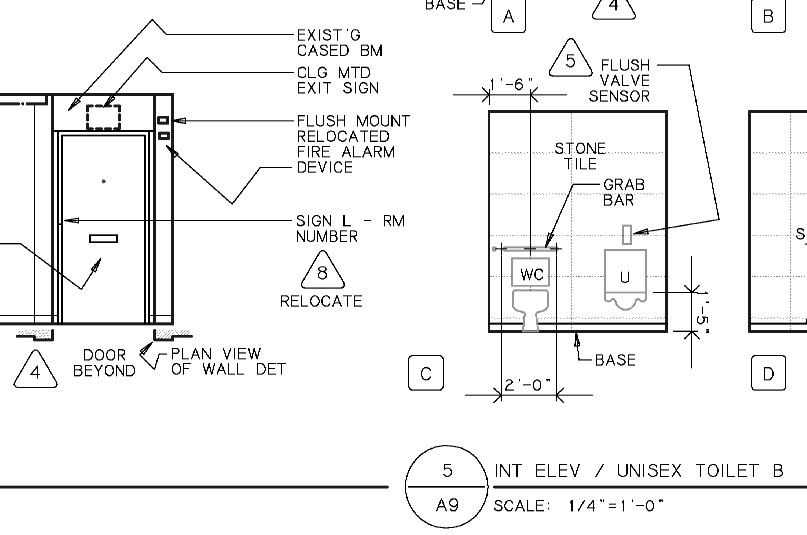
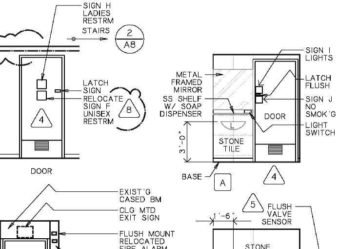
Btw, whats PE stamped? I can't see where you are from and am unfamiliar with that term. I am a licensed Architect in Hawaii, USA. Attached are samples of portions of a 2d production drawing of interior elevations done in the manner I am familiar with. Not pretty, but typical in my part of the world. Perhaps in a room more complicated then this one, unscaled 3d drawings could be inserted between the 2d drawings to add clarity to the set of elevations. Again the problem I would have is with revisions to the design as we are under construction (see delta markings on the drawings below), because the model's 3d view and 2d elevations are not able to parametrically update the 2d labels correctly. The sheet would easily become a mess.
I had the usual problems accommodating revisions to these drawings. In the process I accidentally loss some labels (the door ss kickplate and vent notes), etc. But, nothing out of the ordinary.
-
sketchup for me has killed some of the necessity of note making... what is the point of making a note when you have the entire object built in 3D? why do I have to say "stucco" when you can actual see a stucco texture? why do I have to have a leader and say "switch" if the switch is drawn in such detail. don't get me wrong I still do notes and callouts... but not to the degree I did in AutoCad where everything was simple black and white representations of objects.
I like bMike's drawings... I dimensions differently, but they are fine drawings none the less.
we like to think that are drawings are the final say... but after the foundation is laid, even our dimensions are only secondary generalizations because the field dimension has surely changed ever so much. the point is to provide the instruction.
the whole point of our careers is to relay information to the builders and contractors in order to produce the desired and planned effect... with the economy the way it is and the amount of work it takes to build something in 3D as opposed to 2D... we need to save as much time as possible.
-
@krisidious said:
sketchup for me has killed some of the necessity of note making... what is the point of making a note when you have the entire object built in 3D? why do I have to say "stucco" when you can actual see a stucco texture? why do I have to have a leader and say "switch" if the switch is drawn in such detail. don't get me wrong I still do notes and callouts... but not to the degree I did in AutoCad where everything was simple black and white representations of objects...........
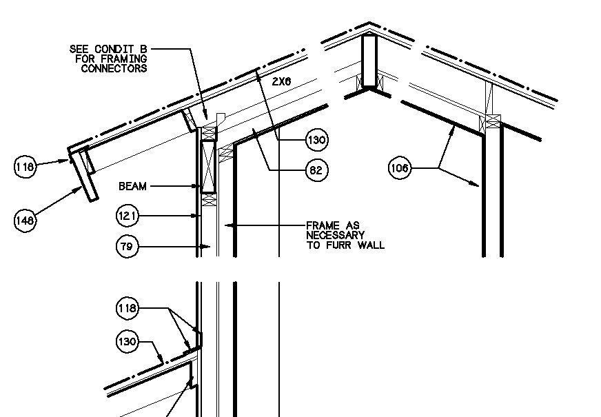
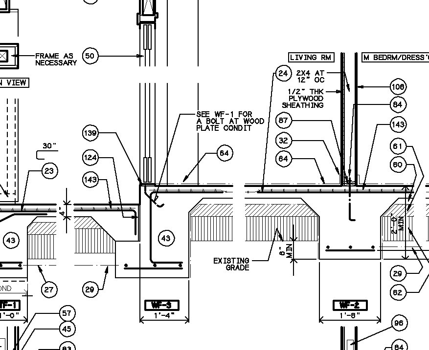
.......the whole point of our careers is to relay information to the builders and contractors in order to produce the desired and planned effect... with the economy the way it is and the amount of work it takes to build something in 3D as opposed to 2D... we need to save as much time as possible.Good points, especially the first. When I went from parallel bar to digitizer, I noticed a propensity for less notes (I thought I was getting lazy, not that the media had improved:-), but it does drive home the point that you don't know until you try. I jumped to Cad without reservation, but am leery about 3d drawings in a production set. Maybe one needs just to start, and the bugs will work themselves out. Krisidious, can you post 100% sized snapshots of interior elevation production drawing (only because that is what the discussion has centered on)? I have had my share of technical failures; the building department, and contractor just loved my use of keynotes (off the the side of each sheet) in these early production drawing samples of 3/4"=1'-0" wall sections.:-(
-
@unknownuser said:
Krisidious, can you post 100% sized snapshots of interior elevation production drawing
oh hell no... I'm not worthy to be posting my construction docs around you architects... I knew I shouldn't have opened my mouth...

-
No way, I have seen your designs. They are fist rate. Production drawings are not the same thing, and I too am not particularly proud of the ones I do. But, consider advancing the "state of the art". Hard to do without visual examples. If you change your mind, just do snippets to illustrate examples.
-
@honoluludesktop said:
The drawing of the lumber shed wall elevation is a sheet from a set of production drawings? I have seen other drawings published here that were credited as production drawings, but like yours did not have drawing labels (A-1/10 North Wall Elevation), drawing scale (scale 1/3"=1'-0"), detail labels and notes (see 5/A-9 for wall header), revision labels etc. I guess I am used to seeing more information as part of a contract document then you are.
Btw, whats PE stamped? I can't see where you are from and am unfamiliar with that term. I am a licensed Architect in Hawaii, USA.
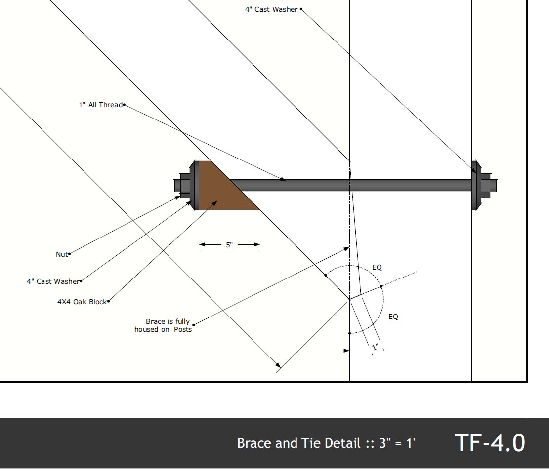
Here are a few details.
I use 'TF-XX' to denote timber structural drawings. In addition to 10+ sheets of mine there were a few extra sheet from the engineer's work for the foundation and another area of the building that has a conventional truss roof.'Bent 1' on the other drawing I posted is referenced on the plan with section indications. A 'bent' in timber design is usually a section of the structure, often across a gable, usually in the short direction. A 'wall' or 'section' is usually used to denote a longitudinal structural assembly. I call these out on the plan, then in the title area, with scale, as required.
PE = professional engineer, in my part of the world (Northeast US).
The PE's portion of the work was similar to the details you show - 2d linework for piers, footers, rebar, etc. I was planning on doing all that work as well, in SKP, but let my PE friend just knock out the work as he is vastly more efficient at running the numbers and designing and calculating as he goes.
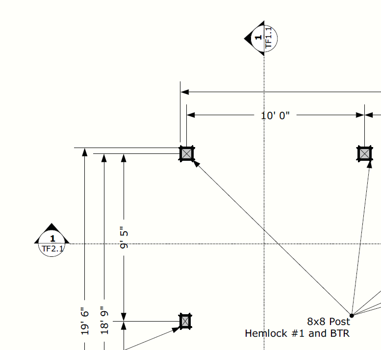
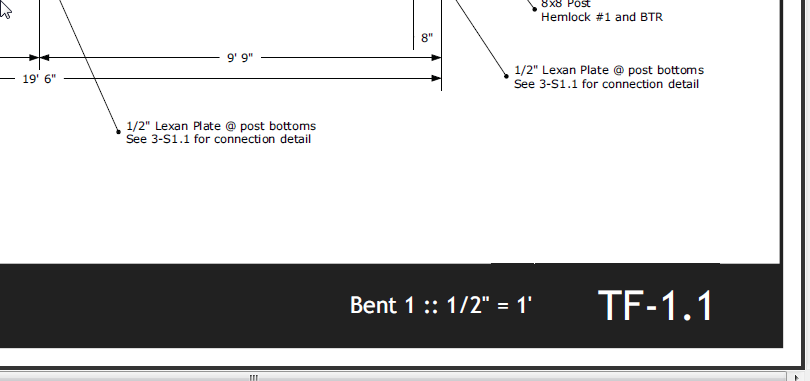

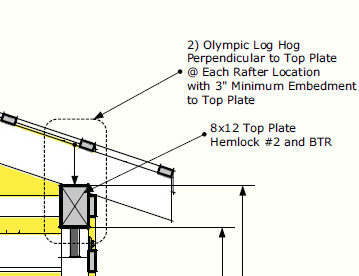
-
bmike, your details are as good as they need get, the color makes them better. A set of plans probably cost more, but are probably worth the added expense. Guess you don't do a lot of interior elevations noting finishes, fixtures, detail references, etc. Did you do the production drawings in SU, and then present them in Layout? How do you coordinate production drawing revisions? Do you update the 3d drawings along with, say a revision to the building sections?
At my current state, once the model is used to present the design, and the job moves into production drawings, the 3d model is abandoned, and the various floor, reflected ceiling, lighting, etc plans only retain a bare amount of common information. While revisions are far better them by pencil drafting, in my case at least they are far from automatic. Do you have a better handle on this kind of drawing coordination?
Advertisement


