sketchucation logo sketchucation
    • Login
    1. Home
    2. skavan
    3. Posts
    ℹ️ Licensed Extensions | FredoBatch, ElevationProfile, FredoSketch, LayOps, MatSim and Pic2Shape will require license from Sept 1st More Info
    S
    Offline
    • Profile
    • Following 0
    • Followers 0
    • Topics 8
    • Posts 26
    • Groups 1

    Posts

    Recent Best Controversial
    • RE: Pool Coping (create tiles between two coplanar curves)

      Eureka.

      Thank you every one.
      As a result of the many inputs on this thread (esp @Dave R)- I now have exactly what I wanted - with very little work! Here's what I did (still some things that I don't understand though):

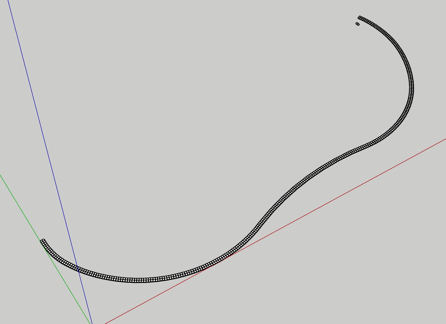
      1. Took the inside of my two lines and offset (the line) it exactly half way.
        (don't understand the benefit of converting it to a Catmull Spline - perhaps Dave R can explain...and when I did it, I noticed some funny loops, so I performed this procedure without that step.)

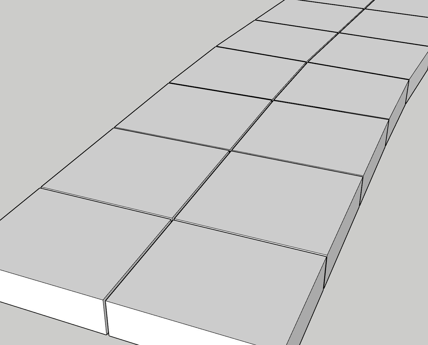
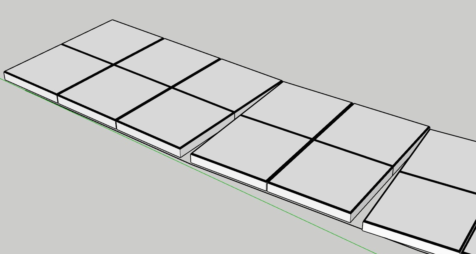
      2. Edited the ruby code of the Stepping Stones.rb, to break the single tile that it creates, into two tiles seperated by the specified gap. While I was tinkering, I put the created tiles in a group.
        Dave R -- when I mentioned that in my last post, I was referring to splitting so I got two stacked tiles. Not the seperation between the tiles.

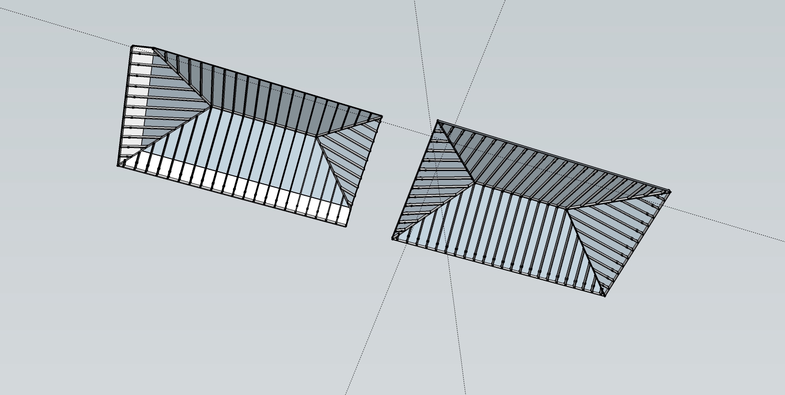
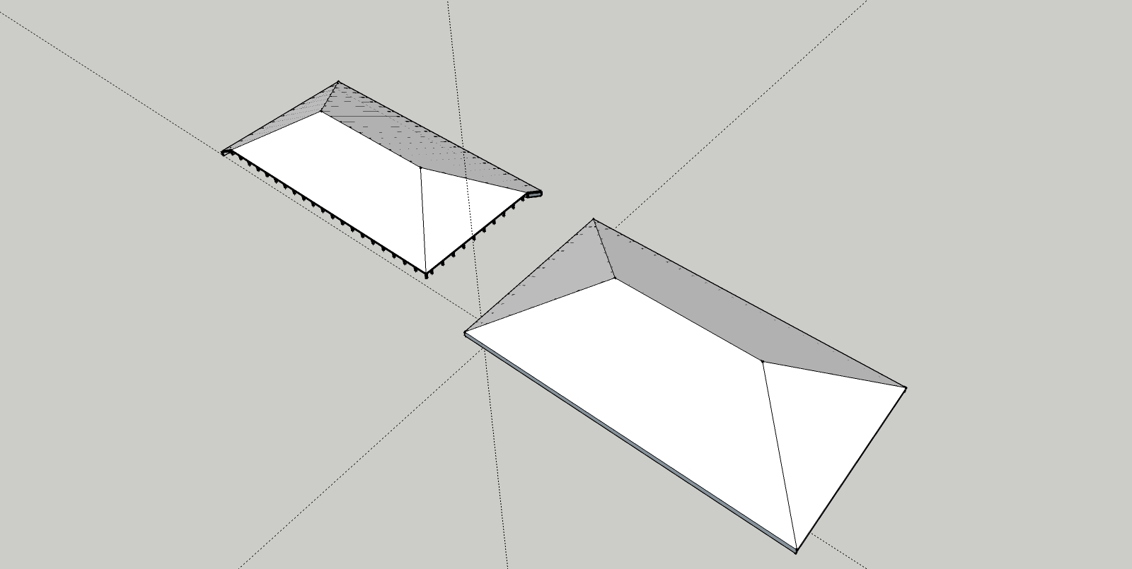
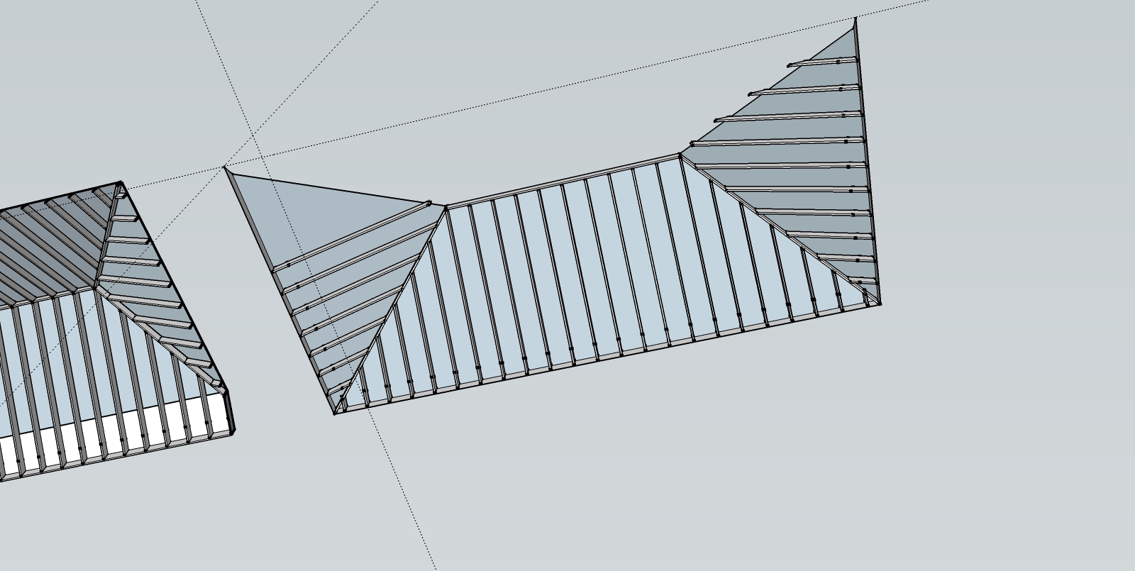
      That's it. Running the script gives me lovely tiles all the way along the coping edge.
      My last remaining challenge is rounding the edges using a v-ray bump map (edgetex), rather than using fredo6 rounded corners, which will create a lot of unneeded geometry. No matter what I try - it doesn't work. I think it may be a v-ray bug.

      Coping Final.JPG


      Pool Coping Edgev2 complete.skp

      posted in SketchUp Discussions
      S
      skavan
    • RE: Pool Coping (create tiles between two coplanar curves)

      So much good stuff in each line of your note! See below:

      @unknownuser said:

      You didn't do what I wrote and adjust the segment length in the curve. As Solo suggested, make the curve the centerline.

      I did do that. At least I'm pretty sure I did.

      @unknownuser said:

      make the curve the centerline

      Cool...but color me dumb - how do I create that centerline. Offset gives me "two" lines. Is there a way to force it to one? If adjust its size to exactly half, both lines disappear.

      @unknownuser said:

      Pilou's suggestion of using Stepping Stones is a good one as it will automatically trim the tiles and leave you with a grout line between tiles.

      Awesome. If I could now figure out a way of cutting those stones with a 1/8" gap on the cut...I'm in business.

      @unknownuser said:

      replacing your curve with a 10s Catmull Spline.

      That's cool too. How did you replace my curve with a 10s Catmull spline?

      posted in SketchUp Discussions
      S
      skavan
    • RE: Pool Coping (create tiles between two coplanar curves)

      You solution is clever -- thanks --- but I am still left with these triangle gaps.
      The damn coping is so big it will be painful to manually deal with them all!
      See pics below.
      This time I am attaching the actual skp file too in case you or anyone can get closer...

      Pool Copibg Edge.skp

      coping 3.JPG
      Coping 4.JPG

      posted in SketchUp Discussions
      S
      skavan
    • Pool Coping (create tiles between two coplanar curves)

      Hi,

      Struggling with this one. Hopefully the pictures will explain:

      My starting point is two paths, imported from a dwg. These paths are for the edge of pool.
      Raw Geometry from dwg

      I need to create coping tiles between the two paths.
      On the inside curve, the length of the tile should be 8". On the outside curve, it does't matter.
      As an added complication, I need to create two rows within the curves.

      I've tried to show the desired result, in this manual section below:
      Intended result

      With the vast array of plugins available, I had thought there would be some way of not having to manually create each tile (which also has a bevelled edge).

      But I am bashing my head against the wall.

      Seems like the steps should be:

      1. Close the curves
      2. Create middle "morphed line" between outer edges (dunno how to do this!).
      3. Move along inside edge, and every 8" draw a perpendicular line until one hits the outside edge. (dunno how to do this).
      4. Take each created face, one by one, and extrude, say an inch. Then apply rounded corner to top face. Move to next face. (Dunno how to do this!).
      5. Put all faces into a group.

      Must be a solution!

      posted in SketchUp Discussions sketchup
      S
      skavan
    • RE: [Plugin] FloorGenerator ( Updated 6-Apr-2017)

      and one more teeny thing for utter coolness is to support an alternating material...for a checkerboard style.
      I can think of two ways of (easily??) doing this:

      1. If different materials are applied to front and back of face and Current Texture is chosen, alternate material, starting with front then back -OR-
      2. If a "special seed value" like -1 is chosen, alternate between the chosen materials in selection via the rand_tex option.

      I hope you can tell that I just LOVE your plugin and am using it to figure out how to tile a 15,000 sq.ft house!

      I promise to stop now!

      posted in Plugins
      S
      skavan
    • RE: [Plugin] FloorGenerator ( Updated 6-Apr-2017)

      Oh gosh - thank you so much that would be awesome!

      If it helps, I have attached a simple SU (2013 for max compatibility) file that shows the concept.
      The polygon on the left is a simple version of a target shape with the desired tile centerpoint shown as the intersection of two guidelines.
      The shape on the right is my current workaround -- which is to force the shape to be equidistant around this target point, and then to go back and trim the excess. This is not too much of a pain on this simple example, but becomes very time consuming when one of the side corridor arms, bends at say 45 degrees! Hopefully it makes more sense to look at than to explain in text!

      Oh - as a tiny cosmetic point, if I choose a tight gap width of say 3/16" (vs. 1/4") it works fine, and is seemingly saved to defaults. When I next open the plugin, it shows as 1/4" not 3/16". I'm pretty sure its storing the right number, but the display is formatted to a single digit fraction. Would be great to expand the formatting to two digits.

      Thanks again for a truely time saving plugin.

      s.


      FloorGen test.skp

      posted in Plugins
      S
      skavan
    • RE: [Plugin] FloorGenerator ( Updated 6-Apr-2017)

      what.a.great.plugin!
      thank you.

      I have a quick question for either the patient author or some of you other experts --
      I want the grid origin to be at a specific point on the face (which is neither the center nor the corner).
      I note in the ruby code, there is this line:
      ctr=face.bounds.center;

      which looks like the line where it picks the center of the face as the origin...any ideas on how to set this instead, to the point where I clicked on the face?

      would make this plugin purffect..

      posted in Plugins
      S
      skavan
    • Ruby access to "hidden" v-ray materials

      Hi,

      When using SU with heavy use of vray proxies, often materials get screwed up and need manual relinking. V-Ray reports which BITMAP it can't load at render time.

      I wrote a tiny script to iterate through the materials collection and query each texture to see if it matches the path of the BITMAP reported above.

      Unfortunately, many v-ray materials (particuylarly those in "multi materials" do not show up in the sketchup collection (including the SU material library window)...and only show in the v-ray material editor. How can I:

      1. Find those materials.
      2. Check any texture paths and compare with the BITMAP path collected above.

      Any ideas?

      Thanks.

      posted in Developers' Forum
      S
      skavan
    • RE: [Plugin] V-Ray Tools

      Hi,

      Odd but hopefully related question:

      I have a large SKP file with loads of both v-ray and non-vray materials in it.
      I note, when I do a distributed render, that it grabs relevant bitmaps from the Network share that the material was loaded from.
      Now, I want to use this file on another network. I (at least I think I) need to:

      1. Find those materials within the project that are v-ray materials.
      2. Copy these materials to a location in my new Network environment.
      3. Replace the impacted materials with those copied in #2.

      Obviously #2 is easy...but how do I do #1 and #3? I can write basic ruby if that helps...your plugin obviously could be the engine, but doesn't offer #1 or #3 as far as I can tell!

      Thanks.

      posted in Plugins
      S
      skavan
    • RE: Replace component and set dynamic attributes?

      OK - getting close -- very close -- but stuck on getting the right rotation (and I'm sure there's a cleaner way of doing all this):

      The issue is that I'm retrieving the wrong rotation. If I create a rotZ attribute on the entity I'm trying to replace, it shows (for example) 135 degrees. But the instance.transformation array gives me a z-rotation of -45. I'm stumped! I've attached a sample scene. The dynamic door is RED and my targets are, well, not.

      door test scene.skp

      ` model = Sketchup.active_model
      entities = Sketchup.active_model.entities
      definitions = model.definitions
      component = definitions['LDOOR']

      model.start_operation("Create Door")
      #create a new instance
      transformation = Geom::Transformation.new([0,0,0])
      componentinstance = entities.add_instance(component, transformation)
      puts 'we have added a new instance (GUID:' + componentinstance.guid + ')'
      $dc_observers.get_latest_class.redraw(componentinstance)
      model.commit_operation

      model.start_operation("XForm Door")
      sel=model.selection
      instance = sel[0]

      x= instance.transformation.origin.x
      y= instance.transformation.origin.y
      z= instance.transformation.origin.z
      
      d= instance.definition.bounds.height
      h= instance.definition.bounds.depth
      w= instance.definition.bounds.width
      r= Math.asin(instance.transformation.to_a[4]).radians.round
      
      componentinstance.transformation = Geom::Transformation.new([x,y,z])
      
      d=2 ;#override depth
      
      #instance.attribute_dictionaries["dynamic_attributes"].each_pair{|k,v|p k;p v;puts}
      ad = componentinstance.attribute_dictionary "dynamic_attributes"
      ad["_lenx_formula"]=w.inspect
      	
      ad["_leny_formula"]=d.inspect
      
      ad["_lenz_formula"]=h.inspect
      
      ad["_rotz_formula"]=r.inspect
      
      $dc_observers.get_latest_class.redraw(componentinstance)
      entities.erase_entities instance
      

      model.commit_operation
      #`

      posted in Developers' Forum
      S
      skavan
    • Replace component and set dynamic attributes?

      OK - here's the challenge.
      I have a model with several non-dynamic components (doors).
      I have a dynamic component (door) called LDOOR.

      I can select all the non-dynamic components -- and then what I want to do, for each such instance is:

      1. grab the height, width, depth and X,Y,Z, and rotation of the non-dynamic component
      2. assign height, width and depth and X, Y, Z and rotation to attributes: LenX, LenY and LenZ,X,Y,Z,RotX etc.. of the dynamic component.
      3. have the dynamic component update itself (i.e. react to the changes in #2)
      4. replace the non-dynamic component with the new instance of the dynamic component.

      It MUST be possible...and I have carefully studied TIG's component replacer code - but try as I might I can't get it to work.

      So far, I can easily select the dynamic component:
      model = Sketchup.active_model definitions = model.definitions component = definitions['LDOOR']

      and I can happily iterate through my selected "non dynamic components":
      sel=model.selection for instance in sel h= instance.bounds.height d= instance.bounds.depth w= instance.bounds.width x= instance.transformation.origin.x y= instance.transformation.origin.y z= instance.transformation.origin.z r= Math.asin(instance.transformation.to_a[4]).radians.round next

      But how to now create a new instance of the dynamic component and fill in the values!!!! H-E-L-P!

      posted in Developers' Forum
      S
      skavan
    • RE: Kill dynamic components?

      @tig said:

      Sketchup.active_model.selection[0].definition.attribute_dictionaries.delete('dynamic_attributes')
      

      just stops the selected DC from being a DC!

      If you have nested DC's within a DC you'll need to run the tool recursively like this

      def dck(c);c.definition.attribute_dictionaries.delete('dynamic_attributes');c.entities.each{|e|dck(e)if e.class==Sketchup;;ComponentInstance};end;dck(Sketchup.active_model.selection[0])if e.class==Sketchup;;ComponentInstance
      

      where the method 'dck' is the 'dc_killer' applied to a selected component AND all of its nested DCs down to any depth... use with care

      I tried pasting this into the ruby editor - but it didn't work 😞

      "Error: #<NameError: undefined local variable or method `e' for main:Object>"

      I'm in SU15. The single line top-level version did work....but I'm really trying to zap the tree.

      s.

      posted in SketchUp Discussions
      S
      skavan
    • RE: How to slice geometry without sections?

      Awesome -- Zorro (now that I understand how to use it!) did the trick.
      TIG's method is a bit more elegant - but a lot more work!

      posted in SketchUp Discussions
      S
      skavan
    • RE: Kill dynamic components?

      @jim said:

      I have a plugin that can "strip DC attributes", optionally delete sub-components which are hidden, and reset the scale mask. I wrote it for a business that uses DC's internally but wanted to protect their IP and reduce file size before making their models public. I have been meaning to get it posted.

      Hi, I know this was a while ago - but any chance I could snag the plugin you reference? Thanks.

      s.

      posted in SketchUp Discussions
      S
      skavan
    • RE: How to slice geometry without sections?

      mmmh....it could be that I am missing something pretty fundamental...but:

      1. When I try and use Slicer it tells me thats its not a Manifold Solid and I can go no further.
      2. If I try and use Zorro, no matter what I try, I can't seem to get the "slicing plane" to run vertically. It always insists on cutting through at an angle.

      The first 2 images below shows the before and after that I am looking for (exactly what a section plane would do - but with real impact on the geometry). If it could cut and delete that would be even better!

      The third image shows Zorro - after choosing a cut line exactly on the Red Axis! H-E-L-P!

      final cut a.jpg
      final cut b.jpg
      final cut c.jpg

      posted in SketchUp Discussions
      S
      skavan
    • How to slice geometry without sections?

      Hi,

      I have a roof (with beams and rafters) in multiple groups. I want to slice off and erase a 3' slice on 2 sides (back and side).

      Pretty easy with a section...but when I export the geometry, I lose the "cut" because the section tool doesn't seem to allow me to "bake" the cut.

      Any ideas? Have searched high and low for a miracle plugin...to no avail. The roof, is NOT a solid.

      I've attached the SU file...would love to get pushed in the right direction - thanks.

      verandah 2008.skp
      s.

      posted in SketchUp Discussions sketchup
      S
      skavan
    • Geolocation woes

      Hi,

      I've searched through the forums for help but either haven't found or haven't been able to translate other answers to my question.

      1. I have a House model that I have carefully built in sketchup. Every so often I pull up the model and refine it and then save it as a component.

      2. I have a dwg of the surrounding land that lays out the 2d outlines of tree positions, driveways and either items.

      3. I have dropped the component on the dwg layer and moved/rotated it as required.

      4. I now wish to pull in geo-referenced terrain.so I go the menu, find the right block of terrain and grab it.

      Now comes the question. What shd I do to line up the dwg and house model such that:

      A. The axes stay aligned to the faces of my house model. So if I draw a path leading to my front door its nicely aligned to the red, green blue axes.
      B. When I update my house model and reload the component, I don't have to realign/rotate everything.
      C. If I grab more terrain it will be deposited in the right place.
      D. if I export the model to 3ds max or vue, the sun will be in the right place!

      I hope that all makes sense.

      posted in Google Earth sketchup
      S
      skavan
    • RE: Sandbox Contours to Solid

      awesome. workes a treat! thx. πŸ˜„

      posted in SketchUp Discussions
      S
      skavan
    • Sandbox Contours to Solid

      OK..so I imported a set of contours and essentially skinned it using the Sandbox tool.
      I want to create the skirt and close the object so it is essentially a solid.

      Once it's a solid, I can perform cut and fill activity on a clone and cmpare the volumes of both.

      Any ideas?

      TIA

      posted in SketchUp Discussions sketchup
      S
      skavan
    • World Coordinates

      Hi,

      I am driving myself nuts. I have a grouped object (created from some contours using the sandbox). When I look at the position Attributes (x,y,z) the results sketchup shows make no sense. For example, the z value is 0 and yet the terrain objects lowest point is 70' off the ground!

      I presume this is because the attributes are reporting some sort of local co-ordinate system as opposed to the world coordinate system represented by the main axis!

      Q1. How do I get the world coordinates? -- and are those coordinates from 0,0,0 to the center of the object?

      Q2. For bonus points -- if I have set a location from google earth, is there any way to translate the coordinates from Q1. into (for example) genuine planetary lat-lon, elevation coordinates?

      posted in SketchUp Discussions sketchup
      S
      skavan
    • 1 / 1