sketchucation logo sketchucation
    • Login
    1. Home
    2. peweuk
    3. Posts
    ๐Ÿ›ฃ๏ธ Road Profile Builder | Generate roads, curbs and pavements easily Download
    P
    Offline
    • Profile
    • Following 0
    • Followers 0
    • Topics 29
    • Posts 138
    • Groups 1

    Posts

    Recent Best Controversial
    • RE: Sort SubComponent List?

      @unknownuser said:

      It sucks when you have repeating SC's that are not next to eachother in the list.

      Here Here !!

      @unknownuser said:

      I might have missed something though.

      I'm not so sure you have. It would be nice if there was an 'up' and 'down' button set to re-order them ๐Ÿ˜’

      posted in Dynamic Components
      P
      peweuk
    • RE: Wall, Door and Window schedules

      @unknownuser said:

      Another idea for a new "tool" would be something where I can take my standard "group" or "component" of a door or window and place it in a wall (which would be nice if the wall was one entity), and then if there was a way to "cut" the wall around the component at the click of a button.

      I think that this is what the 'rectangle_hole.rb' at the Ruby Library Depot already does?

      posted in SketchUp Discussions
      P
      peweuk
    • RE: Wall, Door and Window schedules

      @unknownuser said:

      Be able to draw a standard (preset) height and width, by drawing one line in plan --two surfaces(Just as house builder ruby does for stud walls) .

      @unknownuser said:

      Option to preset offset inwards and outwards of draw line for thickness of materials

      Some of Didier Burs wall tools at the Ruby depot do some of these things,and there are other rubies for making windows and others for cutting holes for them, but nothing that has all the features integrated in one tool. A tool to do this and the other things mentioned would be extremely useful. ๐Ÿ˜„

      posted in SketchUp Discussions
      P
      peweuk
    • RE: Snapping point of components

      Sorted it now. I found the only time the 'edit' window allows changes is if I open the file in which I created the component.

      However a new issue has arisen which I need to look into. I had an 'animate' attribute set in the original component, but having now changed the gluing axis it is doing weird things.

      posted in SketchUp Discussions
      P
      peweuk
    • RE: Output - Selected Attributes of Dynamic Components to CSV

      ๐Ÿ˜ž

      Does anyone know where I might contact someone who may be interested in doing this โ“

      posted in Developers' Forum
      P
      peweuk
    • RE: Snapping point of components

      Oh no ๐Ÿ˜ฎ

      I thought I had found the answer, but after editing a component and saving it the Edit box is greyed out again. ๐Ÿ˜ 

      posted in SketchUp Discussions
      P
      peweuk
    • RE: Snapping point of components

      I found the problem โ˜€
      I am running Vista, and the only way to see the 'Edit' tab when using 'properties' is to open Su with 'run as administrator' ๐Ÿ‘Š

      Who'd have thought it โ“

      posted in SketchUp Discussions
      P
      peweuk
    • RE: Snapping point of components

      Thanks Gaieus.

      I already looked in there - but

      The 'properties' dialog only shows the file location, instances etc, but nothing that can be altered.
      If I select the component and select the 'edit' tab, it shows the 'Glue to' option, but it is greyed out and cannot be changed โ—

      That's what was puzzling me - hence my question. I thought that perhaps the option to change the 'Glue to' state would only be available if a 'Glue to' state had been entered when the component was created - but it is greyed out on one that is set to 'Glue to : any' as well.

      posted in SketchUp Discussions
      P
      peweuk
    • RE: Snapping point of components

      Thanks for that Wo3dan.
      I followed your example making a test panel and it seems to work (don't understand what I was missing before!!!)

      I now have to re-address my existing components to set the gluing plane and axis.

      These are quite complex dynamic components so I was wondering if there is any way to edit the component to change the gluing plane/axis settings without 'exploding' the component and re-making it - as I'll have to re-input all the attributes for them if I have to re-make them.

      (I did a search and seem to be able to find only references to setting these attributes when a component is first made.)

      posted in SketchUp Discussions
      P
      peweuk
    • RE: Snapping point of components

      @unknownuser said:

      If it was an endpoint or midpoint that you moved it by then it will most certainly relocate the snap point for the next component from the browser.

      Sorry, I maybe was not very clear in my response - but there is no problem with the 'snap point' of new components brought in from the browser, even after moving any already placed - it was only trying to move them after they were brought in where the grip on the component being moved was lost.

      I take your point about not having to rotate them when bringing them in - which is what I wanted, but having tried with various settings in the component 'glue' options I still could not get them to work - but I will try again following your suggestions and see what I can do.

      Thanks again for your responses and patience.

      posted in SketchUp Discussions
      P
      peweuk
    • RE: Snapping point of components

      Thanks Wo3Dan, but if I understand your guidance correctly - it does not seem to be the case.

      If I place the component in the scene it uses the correct 'grip'. I then move it by selecting the opposite (top right) corner. When I bring the next component in (same one) from the component browser, it still has the grip in the correct position, bottom left.

      But my problem is with moving it within the scene after it is brought in.

      For example, I have two blocks in the scene, one at 90 degrees to the other.
      I bring in the panel component and 'snap' it to the front of the first block (which is oriented to the red axis). No problem.
      I bring in a second panel, but this has to be 'snapped' to the front of the second block which is now in the green axis direction. So I have to drop the panel on the floor, then rotate it 90 degrees and move it on to the front of the second block. But now the 'grab' point is no longer at the '0.0.0' of the panel component, it is now at the corner of panel itself.

      posted in SketchUp Discussions
      P
      peweuk
    • Snapping point of components

      I have a need to set a snapping point for a component which is 'outside' of the component.

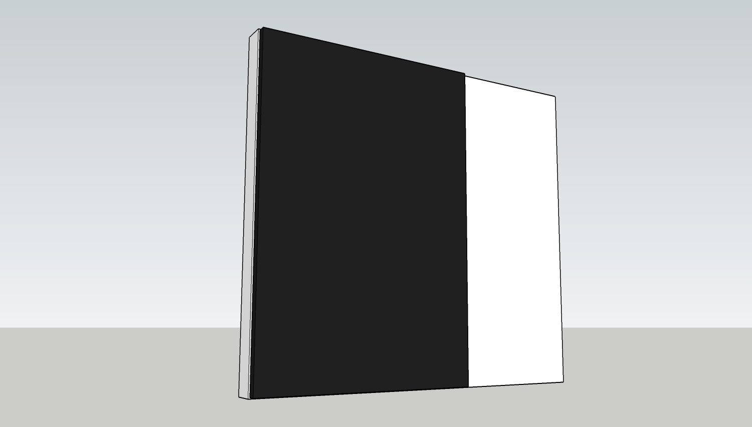
      The image below shows the panel component (the dark panel) and how it needs to be placed in relation to the white block behind it.
      panel1.jpg

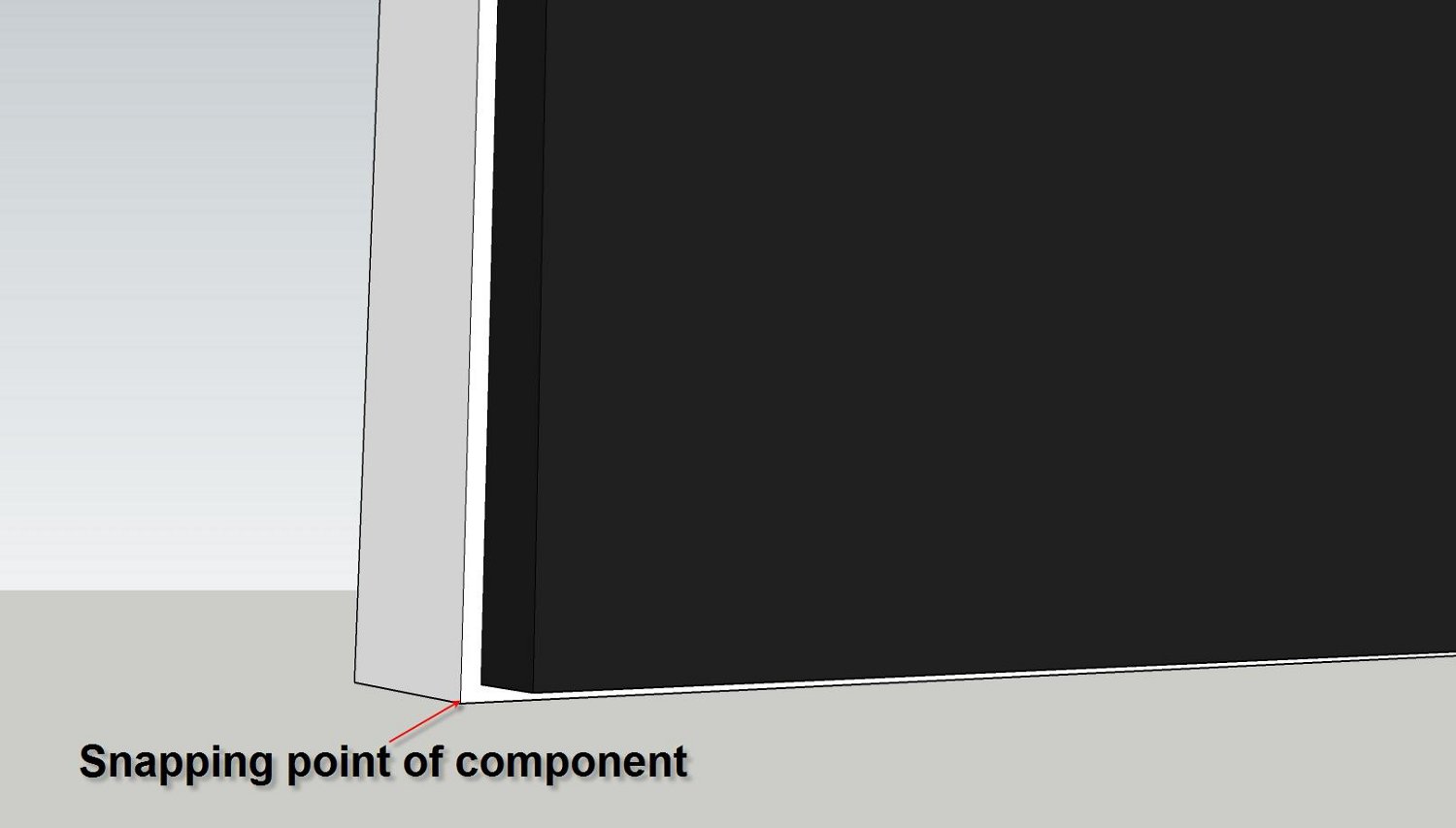
      Here is a close up of showing the position of the panel component more closely - inset from the block corner on the X and Z axis.

      panel2.jpg

      I managed to achieve this by creating the panel component with the axis offset outside of the panel on the X and Z axis, and when it is placed from the component library the snapping position is correct and it is placed where it needs to be (image 2 above).

      However the problem I am having is that as soon as I try to move the panel component, the 'move tool' is snapping to the corner of the panel, and not to a point set away from it (as was the case when the component was first placed from the library). This means that if I move the panel for any reason (say to another block somewhere else in the model) it's snapping point is no longer correct and the panel corner snaps to the block corner and to position it correctly requires further adjustment.

      I hope this explanation makes sense and wonder if anyone can suggest the best way to achieve what I need?

      posted in SketchUp Discussions sketchup
      P
      peweuk
    • Components and Layers

      Is it possible to create a component that is attached to a particular layer.

      For example if I create a component of a table, and it is on a layer called 'diningroom', when the model is saved as a component can the layer 'diningroom' be included so that if it is placed in furture scenes and the layer 'diningroom' does not exist in the scene, it is created and the model attached to it?

      Wishful thinking ???

      posted in SketchUp Discussions sketchup
      P
      peweuk
    • RE: I need an OEM Plug in

      @mkprofiles said:

      I am going to bump this as I am still looking for help

      Not totally sure of everything you are after, but won't the facility of custom fields in Dynamic components introduced in V7 be of use.

      I am no coder, and have not studied all the possibilities in the formulas that can be used in the 'Custom' fields, but if I read your examples correctly, you should be able to add items based on calculations (eg length pricing).

      I had a similar requirement for adding custom attributes and found that the cost of the options available previously was prohibitive, but a breeze in V7 (except for the reporting - but that's the subject of another post http://www.sketchucation.com/forums/scf/viewtopic.php?f=180&t=15052)

      posted in Plugins
      P
      peweuk
    • RE: Output - Selected Attributes of Dynamic Components to CSV

      Thanks for the input Scott.

      I guessed it would be relatively straightforward for a coder - but did not want to be presumptious.

      Let's hope someone my be interested and have some time to do something ๐Ÿ˜‰

      posted in Developers' Forum
      P
      peweuk
    • Output - Selected Attributes of Dynamic Components to CSV

      I know it is early days yet regarding availability of Dynamic components, and I know there are some Ruby Scripts already available for generating reports of component attributes but.....

      With the ability to easily add attributes to DC, particularly custom attributes, it would be nice if there was a way to do a CSV report where the output was specified by the user. For example a script which would display all available attributes of 'selected components' by attribute name, with a tick box for each. If the box is ticked and the report run, a csv file is produced for all the components selected, showing all the attributes ticked by the user. If a component does not have all the attributes which were ticked, the csv column for that attribute is left empty, if it has none of the attributes ticked, the component is ignored for the purposes of the report.

      I don't think such a script exists - if it does I'd be pleased to hear about it.
      I don't even know (not being a coder) if it is even possible and if it is, how complex it would be to write it, but if there are any script writers interested in undertaking a project like this, again -I'd be pleased to hear.

      posted in Developers' Forum
      P
      peweuk
    • RE: Invitation to the SketchUcation collection

      Thanks Dave.

      I'd be interested in any thoughts he has.

      However I don't think it is a plug-in issue.
      I think it is the way that SU allocates its definition of length and width depending on which is the greater ๐Ÿ˜•

      posted in Woodworking
      P
      peweuk
    • RE: Invitation to the SketchUcation collection

      Whilst on the subject of axis and material orientation I have noticed something since I recently started using Cutlist output and wondered if anyone has an answer.

      It seems that SU treats length and width based on a convention of specifying the length as the longest of the axis, which is a problem.

      For example in the attached file I have two panels (one being a streched copy of the other). When I look at the dimensions (in the Get Dimensions plugin or the Cutlist one) the dimension that SU treats as the 'length' is the Y axis on one and the Z axis on the other.

      For material purposes, the grain will be shown correctly in the drawing, but any output will be incorrect as the grain should be running 'lengthways' (the Z axis in the example) in both and SU has swapped the length orientation in the larger panel2.

      It seems that changing the axis has no effect on this and wonder if there is another setting I am missing which will take care of this issue.

      If anyone knows the answer I would really appreciate a pointer in the right direction.

      sizing.skp

      posted in Woodworking
      P
      peweuk
    • RE: Invitation to the SketchUcation collection

      @unknownuser said:

      And component axes should be correct so that the cutlist plugin will yield proper information for purchasing the materials and building the models.

      A point I mentioned in an earlier post.

      There are a lot of woodworkers who are not computer 'experts' and do not have the time to learn CAD, even in it's simplest form, to create their own drawings/models. So a library a catalogue of useful and popular projects which can be 'easily' modified by them rather than them having to start from scratch would be welcomed by many such people.

      However the models have to be 'technically' correct otherwise people lose interest very quickly.

      Ultimately a site with catalogues of projects with instructions/information to help the user work with or modify them would be the ideal - although who would have the time to manage such a project โ“

      posted in Woodworking
      P
      peweuk
    • RE: Invitation to the SketchUcation collection

      @baz said:

      Heres my contribution.
      http://sketchup.google.com/3dwarehouse/details?mid=72c2d871fba975c7d797e188153f356&prevstart=0

      With reference to woodgrain orientation, it always used to be a real pain, but now in su7 you can edit the image in pshop. Simply save the texture as a copy in su. Export it to your image editor, rotate the image 90 degrees and voila!

      Baz

      I am drawing some cabinets to be made from sheet material in V7 and found this useful feature, and that is what I did at first BUT....

      I then decided I wanted the model to work with the cutlist plugin (planning a whole kitchen) and found that to do it this way requires 2 images with different names, one for each material orientation, which causes Cutlist to show the board layout on 2 different sheets (one for each material) instead of one.

      So I revisited the model and changed the axis for the parts which needed it (top, shelf and bottom) and this allowed me to use the same texture for all parts.

      The cabinets are all created as Dynamic Components in V7 (for easy parametric re-sizing) and the alterations to the X, Y, Z sizing was easily done in the Components Attributes window once I changed the axis.

      So if you are designing with a lot of cabinets (such as a kitchen) and are looking to use a cutlist output (either the plugin or a spreadsheet) the axis change is the way to go.

      posted in Woodworking
      P
      peweuk
    • 1 / 1