sketchucation logo sketchucation
    • Login
    1. Home
    2. moot
    3. Posts
    πŸ›£οΈ Road Profile Builder | Generate roads, curbs and pavements easily Download
    Offline
    • Profile
    • Following 0
    • Followers 0
    • Topics 11
    • Posts 52
    • Groups 1

    Posts

    Recent Best Controversial
    • Subtract shape from inside solid

      I'm trying to subtract a shape from inside a solid...
      Core Mold.png

      The shape I am trying to subtract is on the right... I placed a copy inside the solid as reference... that is what I want to 'hollow' out of the solid block...

      I've tried to follow https://help.sketchup.com/en/article/3000100 but can't get it to work... missing something πŸ˜•

      Here's the SketchUp file I'm using: Core Mold.skp

      By chance is there a plugin?... I've tried VisuHole, no luck there... still trying.
      btw, I am using Make... can't afford Pro yet...

      posted in Newbie Forum sketchup
      mootM
      moot
    • RE: Split Face Problem

      Thanks, I'll give it a try. Even though you wouldn't have 'precise' control with arrow keys, it gets you into the ballpark faster and then enter a precise value, imho... guess I'm just used to PhotoShop, Word, methods of moving and modifying images...
      Here is my latest variation... may not be the cleanest drawing... but it prints fine πŸ˜„
      90 deg-Corner-Core.jpg

      Oh, yes, I unchecked all 'snapping'... everything, move, rotation, etc., still seems to jump and I use typed in value...

      Thanks again.

      posted in Newbie Forum
      mootM
      moot
    • RE: Split Face Problem

      Thanks, I think I'm getting the hang of it... one thing I find is that when moving an object, i.e., I'm looking at the bottom of one of the cylinders, any slight movement of the mouse to either side shifts the object... I would like to be able to select the object to be moved and then be able to use the up/down, left/right arrow keys to start moving the object and then type in the distance to move, if necessary... seems like until you start movement in a direction I can't type in a value πŸ˜•

      I did re-do the X-Core and got rid of the 'triangulation'
      X-Core.jpg

      posted in Newbie Forum
      mootM
      moot
    • RE: Split Face Problem

      @dave r said:

      Hmmm... I'm glad it worked but it seems that it was much more difficult than it should be and in your screenshots, you have some triangulation that really shouldn't be needed.

      oh ya, getting the two cylinders aligned was very difficult for me... I noticed that 'triangulation' also... when I pulled the faces to make the X-Core that seems to have closed up. πŸ˜• This is what pulled from...
      X-Core Sm.jpg
      The pics are some of the pieces I need for the 'proof of concept' model I'm working on.
      I have to make others that will include adding a ~12[sup:1t7rp2vh]o[/sup:1t7rp2vh] cylinder coming out from the top of the tee... and other variations for a variety of 'connectors'... anyway, although the extra geometry is not needed, the pieces print and that is what I need to get done now. These models are primarily needed to do the sand casting molds, the drawings can be fixed later, if needed.

      @dave r said:

      Do you want just the tee without the extension of the crossing cylinder that you have in your original image and like I drew?

      I appreciate the offer... but I don't want to impose on your time... you've given me quite a lot of help already... and I'm sure I'll need more πŸ˜‰

      How 'bout some idea's on an easier way to 'align' pieces? πŸ˜•

      I'm just about to try figure out my outside-corner-tee-with-12[sup:1t7rp2vh]o[/sup:1t7rp2vh]-core... needs to be like the X-Core with one cylinder folded up 12[sup:1t7rp2vh]o[/sup:1t7rp2vh] from horizontal...

      posted in Newbie Forum
      mootM
      moot
    • RE: Split Face Problem

      @dave r said:

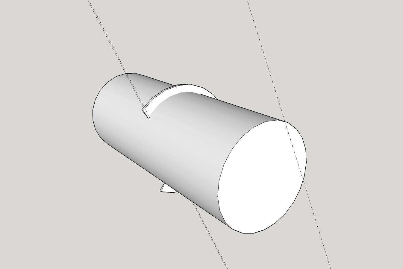
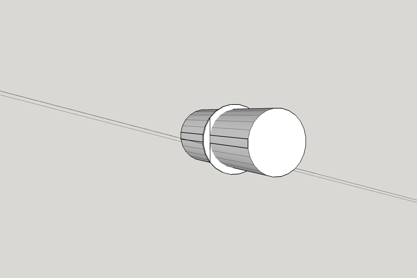
      There are plugins to do that but it's certainly not difficult to do it with native tools. After intersecting the cylinders, I just hide an end of a cylinder and delete the internal faces by selecting them and hitting Delete. I would suggest you learn to do it that way before you start looking for an extension to do it.

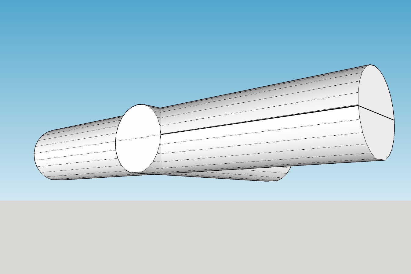
      I was trying... I wrestled with the 'intersecting'... got frustrated... what I ended up doing was starting over (as suggested in other posts)...

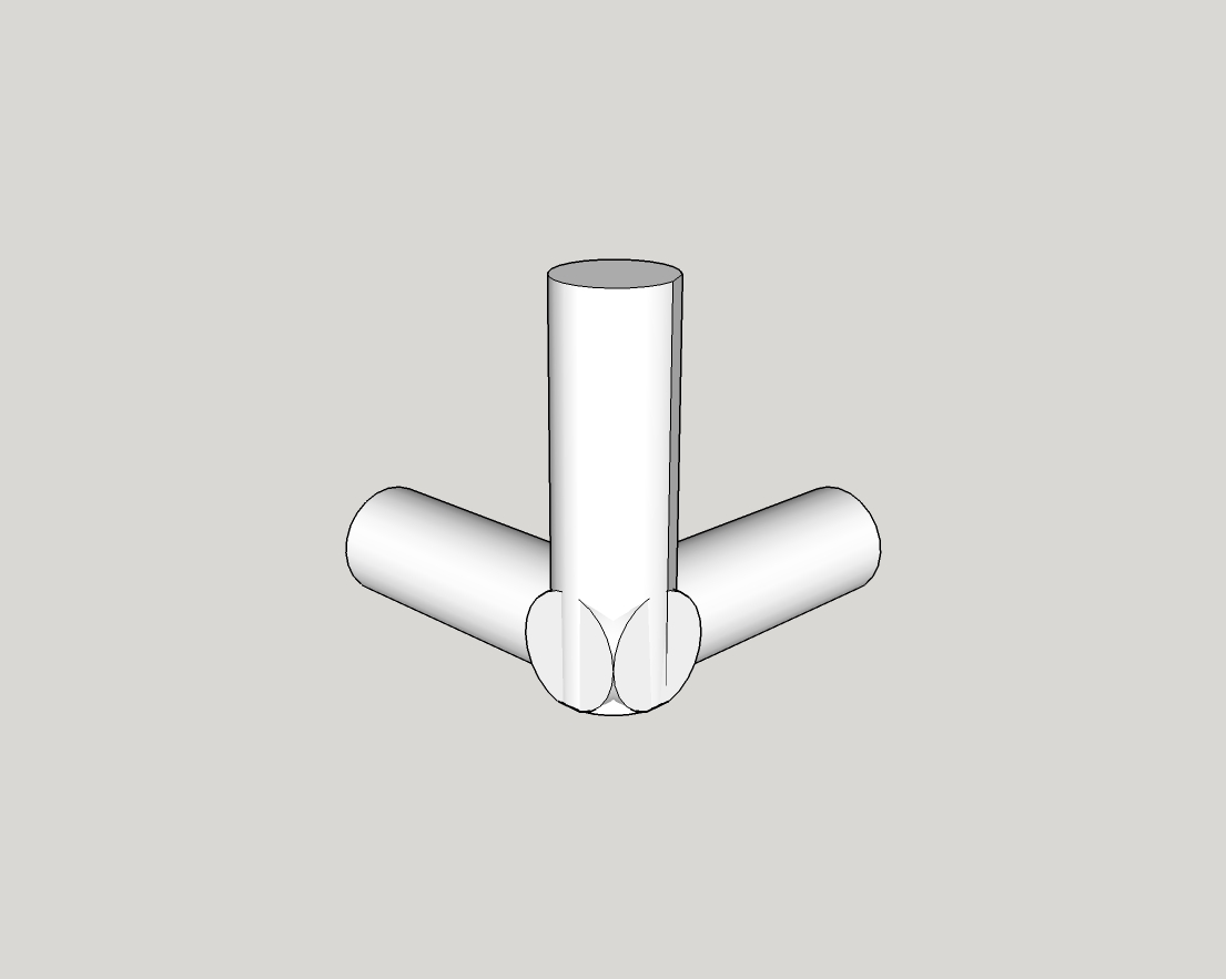
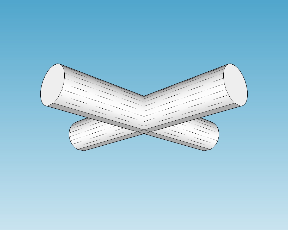
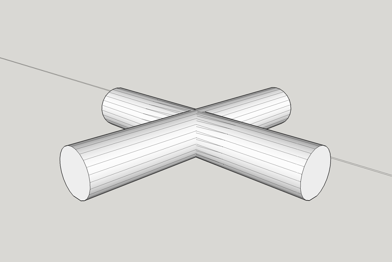
      I took my original Strt-Core,
      Strt-Core.jpg
      saved as X-Core,
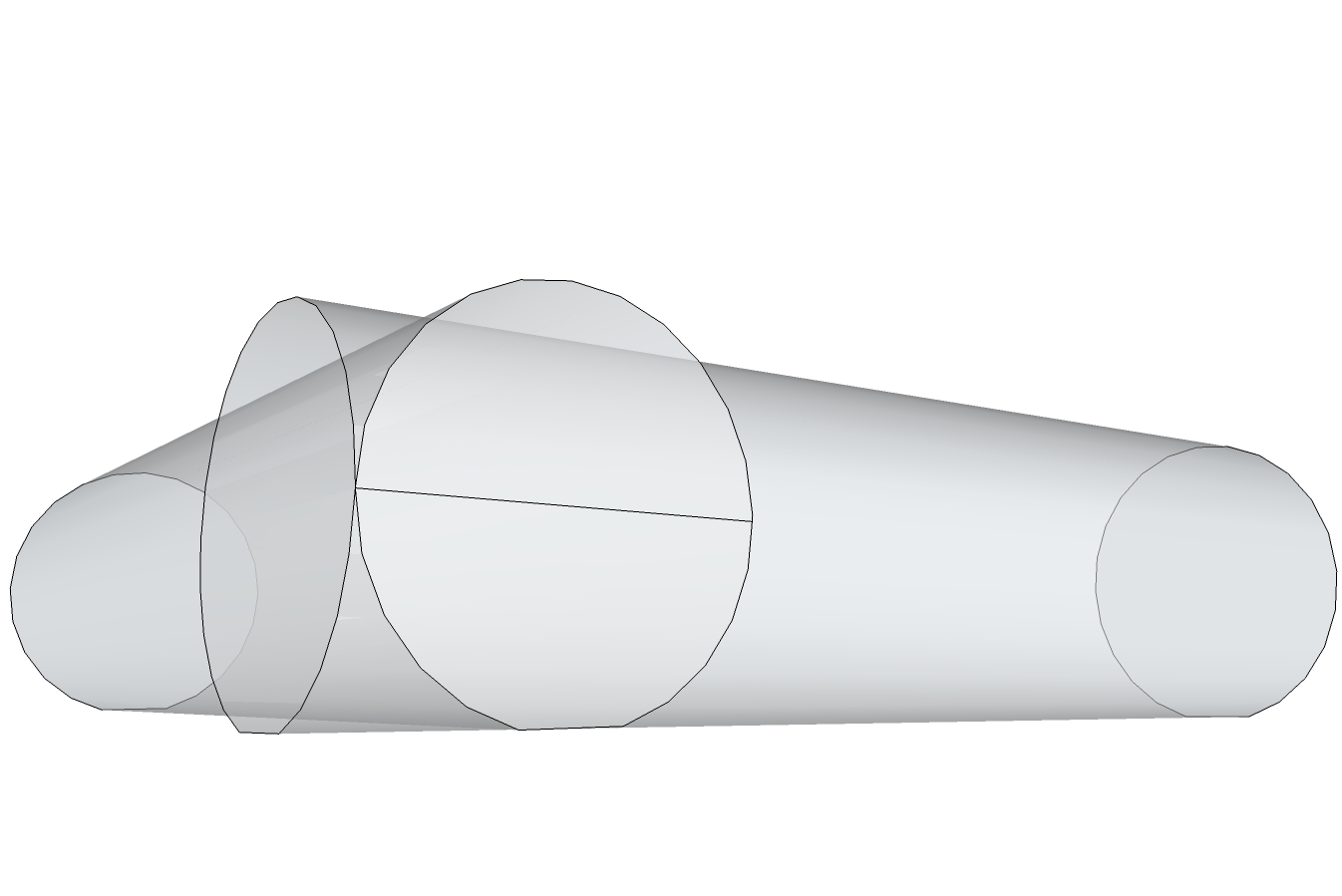
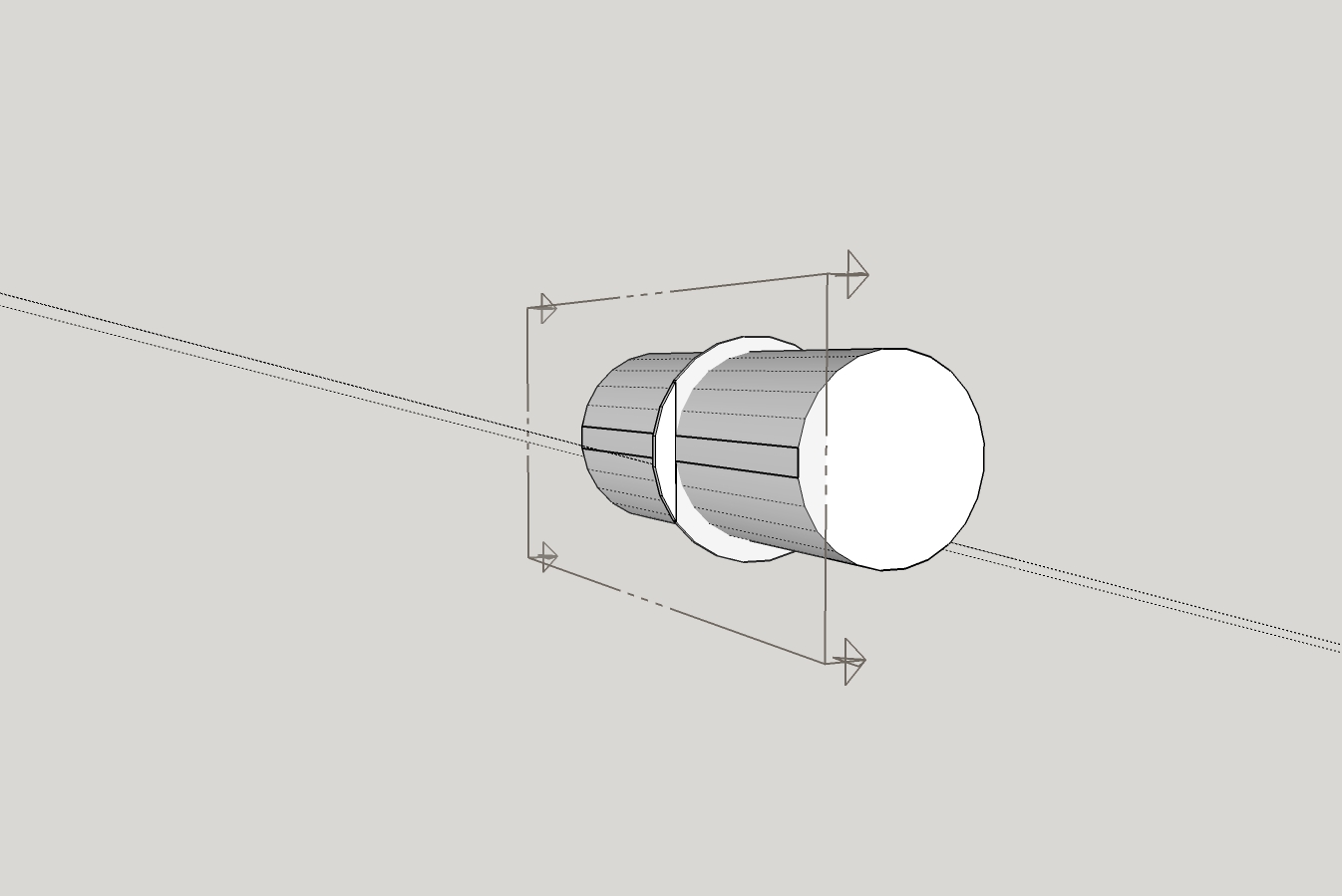
      made a copy of the cylinder, rotated it, and placed it into the other cylinder and pulled the ends/faces of the cylinders until I got the length I wanted...
      X-Core.jpg
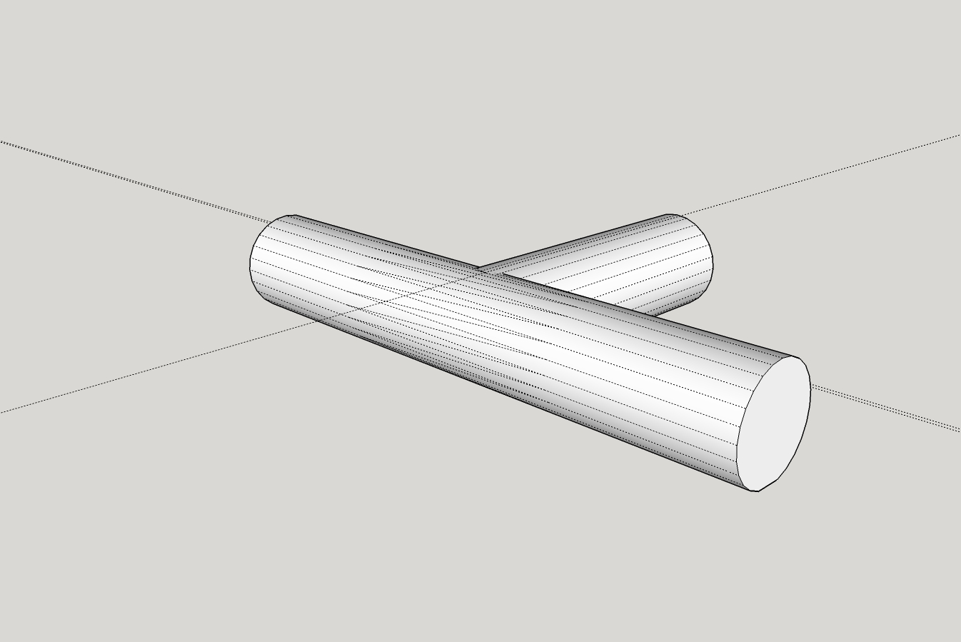
      The real problem I had was that when I printed, one cylinder in the model was .0xx above the axis of the other cylinder... it took me a few 'move' operations to get both cylinders on the same horizontal axis in order to print properly... which leads me to ask, is there any tool to 'align' objects to one axis, i.e., the bottoms of the cylinders will lay flat on the build table when built?

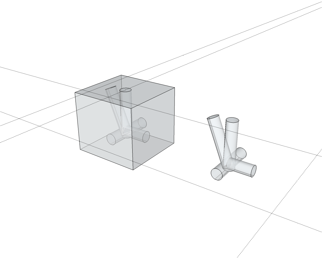
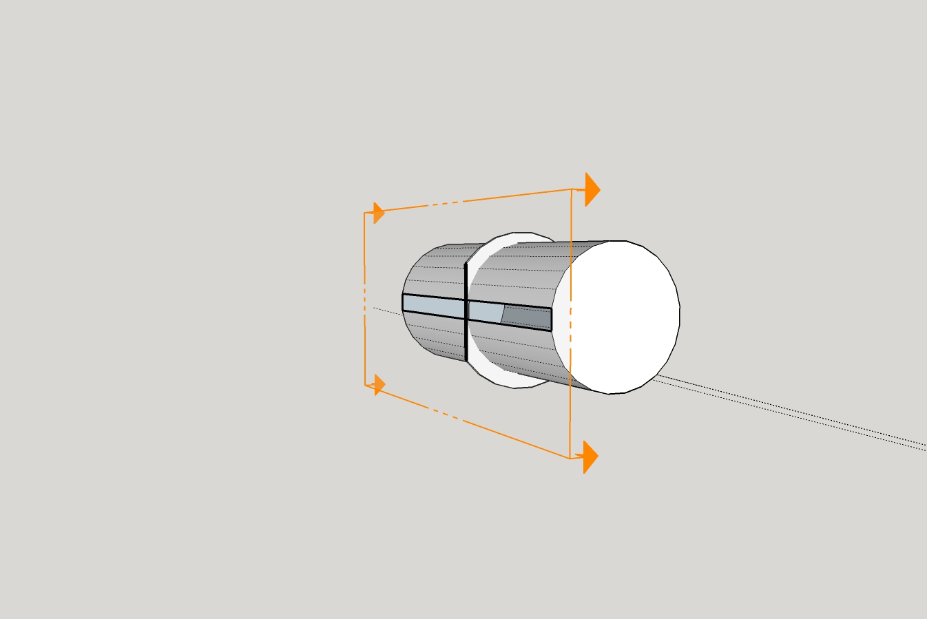
      Once I got the X-Core right I was able to save it as my Tee-Core, push the face of one cylinder into the center of the crossing cylinder and it printed fine. πŸ˜„
      Tee-Core.jpg

      Thanks for all the help in giving me some clues/tips... I still have a lot to learn (like how the transform stuff works), but at least I think I'm making some headway in rough seas...

      posted in Newbie Forum
      mootM
      moot
    • RE: Split Face Problem

      Will do, thanks...

      posted in Newbie Forum
      mootM
      moot
    • RE: Split Face Problem

      Thanks again, you make it look easy πŸ˜‰
      I did searches on rove internal faces but looks like plugin?
      Can you recommend one?

      posted in Newbie Forum
      mootM
      moot
    • RE: Split Face Problem

      When I saved the 90 deg-Core.skp SU gave me the option to fix problems... I did.

      When I load the 90 deg-Core.stl into the printer software (Dremel3D Idea Builder) I do not get any error(s) or warning(s) about open faces and the model prints fine.

      When I pull the face(s) (as shown in Tee-Core.jpg) I end up with the 'open face(s) in model' issue.

      @wo3dan said:

      ...Unless you intersect the two cylinders, the edge needs to be there. It is part of the round surface. Turn on X-Ray to see the other edges.

      I added two lines (where to halves were split) and then did a select all, selected Intersect, With Model... When I tried to load model, I got the 'open face(s)' error...

      So, any hints on what I'm doing wrong? πŸ˜•

      posted in Newbie Forum
      mootM
      moot
    • RE: Split Face Problem

      Thank you, good tip... but I still have the problem that the face is still split...
      If I enter the edit mode for the group, select the Push/Pull Tool, only half the circle is selected for, in my case, trying to pull the face to make it longer... I have to pull each half... when I tried that the halves were not 'joined' πŸ˜• , so the model ended up with an open face and can't be printed. I would have to manually try to close the face...
      Tee-Core.jpg
      Tee-Core.skp
      PS, like your animation... how did you do that?

      posted in Newbie Forum
      mootM
      moot
    • Split Face Problem

      Tried, but cannot figure out how to get the 'split' out of the face(s)... I would like to see it as one face... like all the others...
      90 deg-Core.jpg
      90 deg-Core.skp

      posted in Newbie Forum sketchup
      mootM
      moot
    • RE: Sections

      Thank you very much... All dimensions/measurements are as in the .skp in my first post.
      Very tight tolerance required for fit... am still making .00x mm adjustments and do have questions about ability of SU to 'modify' objects, i.e., radius, segments,etc. I'll start another post/thread.

      123D Design has a 'Smart Scale' that works pretty good, but (can't say it to often) it is just plain hard to use, in my humble opinion πŸ˜‰

      I testing a Dremel3D20, got 60 days to torture it... I'm on the cusp as whether to return it or not...

      posted in Newbie Forum
      mootM
      moot
    • RE: Sections

      That would be it, a lot cleaner than what I came up with. Flat on core is nice, I was thinking of doing that because I plan on putting a stamp, 12.7mm deep in bottom of core.
      Strt-Core and Ring4.jpg

      Thank you for taking the time.
      I used the Zorro2 plugin, but had a little difficulty... left open face(s). I did finally get things closed up and SolidSolver verified that it was a Solid πŸ˜„

      Printing it now.

      PS, I would be interested in seeing your .skp β˜€

      posted in Newbie Forum
      mootM
      moot
    • RE: Sections

      Really, that is what I am trying to do... maybe I'm getting to old... or just dumb... πŸ˜•

      posted in Newbie Forum
      mootM
      moot
    • RE: Sections

      @dave r said:

      A section plane does not cut geometry. It only gives the appearance of it being cut away. If you are actually trying to cut a flat on the side of your shape, you need to use something else. You can use a face intersected with the geometry or you could use an extension like Zorro2.

      Ok... I'll get that plugin/extension... I'll check the PluginStore...

      posted in Newbie Forum
      mootM
      moot
    • RE: Sections

      @driven said:

      is it meant to be completely out of square?

      john

      Not quite sure what you mean? The core is round, the ring is round, at least as far as I can tell. It appears to me that the plane is cut right along a face of the core and thru the ring where it sits on the core's face... could be wrong πŸ˜‰

      posted in Newbie Forum
      mootM
      moot
    • RE: Sections

      @pilou said:

      If you want Print 3D your object you must make some thickness to all faces who have not! πŸ€“

      I realize that. Closing the open faces is the next step I will tackle... but first I have to get rid of that reverse plane portion...

      posted in Newbie Forum
      mootM
      moot
    • RE: Sections

      Turned off both... same result... model ring is all the way around... not what I want.
      I've been trying to figure out 123D Design. There is a 'slicing' tool but I have not had any luck in getting that to work... yet... 123D Design is not very user friendly, for me anyway 😞

      posted in Newbie Forum
      mootM
      moot
    • RE: Sections

      @box said:

      Perhaps you just need to select, View and untick section planes and then save the file.
      Or export the result as a 2d image.
      It is unclear what you want.

      That is just the issue I am having... I cannot just select the active side of the plane cut... and save the file... the file still has the reverse side... still part of the model.

      What I want is to be able to export (what is visible) to an .stl file and print it on my 3D printer. If I Export to STL, the resulting file will have the ring all the way around the core... when loading to my printer software, it will be red, meaning that, because the ring is siting on the table and the core is 'floating' without support it cannot be printed (unless I rotate it on core end). Printing it will still print the whole ring.

      @dave r said:

      I can see the same thing you show in your screen shot so evidently you saved the file just fine. If you want the section cut without the section plane, you can turn off the plane in the Styles edit window or the sections toolbar. You should update the style with the changes, too.

      As soon as you turn off the plane you get the whole circle - not what I want.
      In effect I want a model that has the same shape as the picture (in first post)... and have it print like that.

      Strt-Core and Ring3-View Plan Off.jpg

      Strt-Core and Ring3-Plan not active.jpg

      Strt-Core and Ring3-Reverse plane.jpg
      Trying to make it clear... I want to slice off the reverse plane and erase it.

      posted in Newbie Forum
      mootM
      moot
    • Sections

      I'm stuck... I got to section cut, active, and what is displayed is how I want the final model to look - but - cannot figure out how to save it πŸ˜•

      This is what I want my model to look like:
      Strt-Core and Ring3.jpg
      Strt-Core and Ring3.skp

      posted in Newbie Forum sketchup
      mootM
      moot
    • RE: [Plugin] SolidSolver

      @pilou said:

      ... Put here the adress' file that you will receive!
      ... without image and or file we can't answer intelligent things! πŸ˜„

      https://we.tl/WGhEM1EcdA

      Hope I did it right... Don't know if the comments show up, so here's a little explainer:

      β€˜Reason for base - Dremel3D printer moves leg off build table... results in rats nest’

      I am using this model to test the Dremel3D20... seems like a fairly complicated build, having to span the legs to build the body and do the tail... this is just a test πŸ˜‰ ... and to learn SketchUp (and 3D design, in general)

      posted in Plugins
      mootM
      moot
    • 1 / 1