sketchucation logo sketchucation
    • Login
    1. Home
    2. gregw
    โ„น๏ธ Licensed Extensions | FredoBatch, ElevationProfile, FredoSketch, LayOps, MatSim and Pic2Shape will require license from Sept 1st More Info
    G
    Offline
    • Profile
    • Following 0
    • Followers 0
    • Topics 0
    • Posts 8
    • Groups 1

    gregw

    @gregw

    10
    Reputation
    1
    Profile views
    8
    Posts
    0
    Followers
    0
    Following
    Joined
    Last Online

    gregw Unfollow Follow
    registered-users

    Latest posts made by gregw

    • RE: 3Dconnexion SpaceMouse Zoom Behavior

      @gamelon said:

      Thanks, gregw. Works like a charm. Is there some documentation describing this or other combinations?

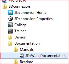
      The documentation should have been installed when you loaded the 3Dconnection drivers. On my windows computer it's in the start menu under 3Dconnexion > Documentation.

      For what it's worth here's a few things that work well for me using the spacemouse with Sketchup:

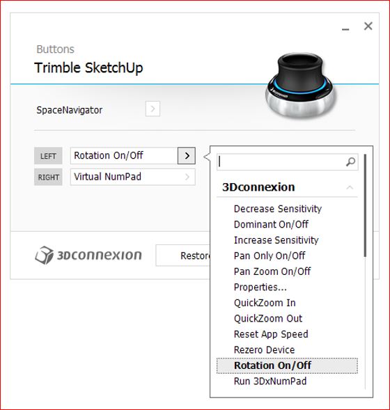
      Assign one of the buttons to "Rotation On/Off" so then you don't have to hold the middle mouse button down to lock the rotation.

      Make a template file with the camera set to parallel projection and with scene tabs setup with the standard views so you can easily zoom and pan in any desired 2D orientation by selecting the scene and then using the assigned button to lock the rotation.

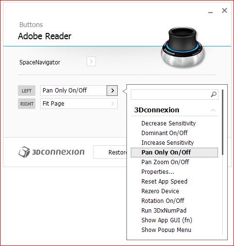
      The spacemouse also works great with adobe acrobat. I use a dual monitor setup and I normally have reference info in pdf format on one screen. I set the left button on the spacemouse to lock and unlock the zoom in the 3Dconnexion Acrobat settings when I select the acrobat screen.


      3dx docs.JPG


      SpaceMouse.JPG


      Acrobat spacemouse.JPG

      posted in Hardware
      G
      gregw
    • RE: 3Dconnexion SpaceMouse Zoom Behavior

      You can take advantage of the 3Dconnexion Fast Zoom or Zoom to Cursor option by holding the middle mouse button down while moving the 3Dconnexion cap back and forth.

      posted in Hardware
      G
      gregw
    • RE: Tube coping template wrappers

      it's been many years since I've used one,but we used to call them "pipe saddle templates". We would make a pattern out of sheet metal and then trace it onto a piece of paper.

      posted in Newbie Forum
      G
      gregw
    • RE: [Plugin] ZoomWindowSelect_dj.rb Ver. 1.0.2

      Thanks James, it's perfect...sort of scary though, almost like you read my mind ๐Ÿ˜‰

      posted in Plugins
      G
      gregw
    • RE: Matching curved surfaces (inside mitre on crown moulding)

      select the path first and be sure to include the top edge of your extrusion profile..and then it should work using the follow me tool

      posted in Newbie Forum
      G
      gregw
    • RE: Sketchup 8pro and surveying/drafting

      @eddix99 said:

      The great thing about doing things within sketchup is that you can simply just grab the rotate tool and realign your data so that it fits. This means that you can get away with getting your backsight sorted AFTER you do your survey. As long as the data is in the right position from the station I would imagine it to be pretty easy to align it with existing points.

      Edward,

      That's the key..making sure you have enough good reference data to align the data properly. If you establish fixed reference points around the perimeter of the site you should be able to add as many additional stations as necessary.

      The fixed points will need to be stable, and they can be something temporary like a ground stake. Once you establish the location of the reference points you can always go back and add more stations/measurements to the survey as required.

      If you have problems with the lines intersecting you can always use construction points instead. You only need the endpoint from the instrument measurement lines and you can create those using the construction point tool.

      The XYZ coordinate concept is pretty simple..In the Sketchup 3D coordinate system points in space are identified by position along the three drawing axes:

      +X is the solid red line, -X is the dotted red line (right - left)
      +Y is the solid green line, -Y is the dotted green line (in - out)
      +Z is the solid blue line, -Z is the dotted blue line (up - down)

      One thing I did notice is that looking at your Sketchup file it looks like you have the axes rotated so that the +Z axes is pointing down..I'm not sure why it's that way, but it is opposite of how it normally would be.

      I don't know what the site your mapping looks like or what obstructions there are, but I added generic alignment point locations to this picture of your layout to show you what I'm talking about..as well as a view using construction points in place of the measurement lines.


      fixed alignment points added to site plan


      construction points in place of lines

      posted in Newbie Forum
      G
      gregw
    • RE: Sketchup 8pro and surveying/drafting

      Hi Edward,

      Another option you might want to try out is the polar line plugin by Matt666...it looks like it will allow you to enter your azimuth and distance readings directly to input the survey measurements into your sketchup file, so you wouldn't need to convert the azimuth to a bearing.

      http://forums.sketchucation.com/viewtopic.php?f=323&t=10997&hilit=polarline

      Regardless of which method you use (azimuth/distance, bearing/distance, or coordinates) here is one way to orient the measurement data from multiple instrument locations in sketchup.

      1. enter the measurements from the first station location into sketchup

      2. draw lines between the resection points you measured from station1 to orient it with station2

      3. Select all and make a group/component called "station1"

      4. Hide the station1 group/component and then repeat steps 1 through 3 for the station2 data

      5. unhide the station1 group/component

      6. use the move tool to reposition the station2 group/component by grabbing the midpoint of the line you created between the resection points and moving it to the corresponding line midpoint in the station1 group/component

      7. use the rotate tool to complete the alignment of the station2 group/component by rotating the group about the midpoint of the station2 resection point line to make it align with the corresponding resection point line in the station1 group/component

      8. Now that the two stations are aligned you should check the distance between the corresponding resection points to ensure that you have an acceptable alignment.

      here are a few things you may want to consider when performing the measurements...

      Even though you can align the data using two points you should measure at least four resection points. The redundant points can be used to validate the alignment and also to achieve a better alignment if necessary.

      Ideally the resection points will lie outside of the boundary of the object your measuring, the span between the points should be greater than the distance between the two stations you are trying to orient, and the most accurate result is achieved when the apex angle formed by the station you are orienting and the resection points is 90 degrees.

      The measured relationship between the resection points will be slightly different from any two stations.. all of the variables (environment, instrument and target tolerances, etc..) are never going to let you get the same exact readings twice. Using the midpoint of the line created between the resection points allows you to average some of the error between the sightings, but the accuracy achieved from performing a two point resection alignment may not always meet your requirements.

      posted in Newbie Forum
      G
      gregw
    • RE: Sketchup 8pro and surveying/drafting

      @eddix99 said:

      One thing that the survey tool ruby doesn't do is allow me to move the axis to another location and begin plotting distance/bearing from that new location. This is a real pain as it means that I cant move to another station and continue my survey from there.

      If there are others out there that are into the surveying ruby, how do they get round these limitations?

      Hello,
      I don't have any experience using the survey tools plugin but I do have a bit of experience using survey equipment so I thought I would offer a few ideas..

      I'm not sure exactly which total station you are using but I think that some of them allow the measurement data to be output in rectangular coordinates (x,y) relative to the instrument location. The rectangular coordinates would allow you to easily enter the measurement data into your sketchup model and it would also allow you to orient the new station locations to your existing data by measuring three known (previously measured) non linear points from the new station location.

      Even if the total station you are using doesn't output rectangular coordinates it's easy to convert the instruments polar coordinates to rectangular by using a simple formula.

      posted in Newbie Forum
      G
      gregw