sketchucation logo sketchucation
    • Login
    1. Home
    2. DavidBoulder
    3. Posts
    ℹ️ Licensed Extensions | FredoBatch, ElevationProfile, FredoSketch, LayOps, MatSim and Pic2Shape will require license from Sept 1st More Info
    Offline
    • Profile
    • Following 0
    • Followers 0
    • Topics 38
    • Posts 343
    • Groups 1

    Posts

    Recent Best Controversial
    • RE: [code] intersect_with example

      Thanks, that was really helpful, but I'm having problems with a simple variation on this.

      The basic concept is a model with only groups at the top level. The user selects a group and then runs the script. The script should intersect that group with the model; the new geometry is created inside of that group. My next step after this is working is to let the user multi-select and iterate through their selection. That should be easy if I can just get the basic code working first.

      This is what I want for the intersect_with line, but I just can't get it to work. I guess I need to get the name of the group that is in selection[0]? and then use that similar to your code.

      selection[0].intersect_with true, selection[0].transformation, selection[0], [0,0,0], true, entities

      posted in Developers' Forum
      DavidBoulderD
      DavidBoulder
    • RE: Loop.convex? question

      Thanks for the feedback. The data file that is drawing my geometry in the first place already has a smaller list of verticies that is clean. So I guess that is the best option, going back to that, drawing a temporary face to test, and throwing it away. I don't know how much of a performance hit that will be over testing an existing face. But what I can do is pre-test with the existing face, and then only create a temporary face to test on the ones that initially fail.

      David

      Below is the code I ended up with. My SketchUp objects are drawn from data in an external file. I could have drawn temporary faces for convex test for every surface but decided to do the initial test off of the existing SketchUp faces, and then do a second test on faces that fail the convex test to confirm that they really are non-convex. This second test goes back to the data file, draws a temporary surface, tests it, and throws it away. The data file is already fee of un-necessary stray points.

                     if @hash['NON_CONVEX_SURFACES']
                     face = interior_partition_surfaces[index].entity
                     loop = face.outer_loop
                     status = loop.convex?
                       # if face is convex skip over it
                       if status
                         next
                       else
                         # failed first convex test, run second one
                         pointstemp = interior_partition_surfaces[index].model_object_polygon.points
                         model = Sketchup.active_model
                         entities = model.active_entities
                         facetemp = entities.add_face pointstemp
                         loop2 = facetemp.outer_loop
                         status2 = loop2.convex?
                         # erase facetemp
                         facetempall = facetemp.all_connected
                         entities.erase_entities facetempall
                         if status2
                           # next statement skips the rest of this if face is convex
                           next
                         end
                       end
                     end
      
      
      posted in Developers' Forum
      DavidBoulderD
      DavidBoulder
    • RE: Loop.convex? question

      Kind of a related question. I have a source data file that has clean versions of for example the floor that has only 4 verticies vs 6 (2 extra for the door). An alternative approach is to bring in those verticies, and do a loop.convex? test on them. But it appears I have to make a face before I can make a loop? Any way to do that without actually drawing a face. Otherwise, I can draw and erase a face, but seems like it would slow things down.

      posted in Developers' Forum
      DavidBoulderD
      DavidBoulder
    • Loop.convex? question

      I was experimenting with loop.convex? and found that extra co-linear points make a surface fail this test. As a result for example if I had a rectangle that I extrude it up, and then draw a rectangle on the bottom edge of one of the side surfaces that represents a door; the floor which would have otherwise passed the convex test, now fails it. I made a variation on the sample code in the API documentation to demonstrate it. Does anyone know an easy way to catch these cases so they don't fail?

       depth = 100
       width = 100
       model = Sketchup.active_model
       entities = model.active_entities
       pts = []
       pts[0] = [0, 0, 0]
       pts[1] = [width, 0, 0]
       pts[2] = [width, depth, 0]
       pts[3] = [0, depth, 0]
      
       # Add the face to the entities in the model
       face = entities.add_face pts
       loop = face.outer_loop
       status = loop.convex?
       if (status)
         UI.messagebox "Loop is Convex"
       else
         UI.messagebox "Loop is not Convex"
       end
      
       ptsB = []
       ptsB[0] = [200+0, 0, 0]
       ptsB[1] = [200+width/2, 0, 0]
       ptsB[2] = [200+width, 0, 0]
       ptsB[3] = [200+width, depth, 0]
       ptsB[4] = [200+0, depth, 0]
      
       # Add the face to the entities in the model
       face = entities.add_face ptsB
       loop = face.outer_loop
       status = loop.convex?
       if (status)
         UI.messagebox "Loop is Convex"
       else
         UI.messagebox "Loop is not Convex"
       end
      
      posted in Developers' Forum
      DavidBoulderD
      DavidBoulder
    • RE: Technical in sketchup/ layout

      I've also used fog to create a depth map that can then be used to create a mask to control contrast or color of an elevation.

      I set my model to be white, lines just off white (was a glitch if they were white), and fog in black.

      posted in SketchUp Discussions
      DavidBoulderD
      DavidBoulder
    • RE: Rotate Axes w/ top down view

      I often save a rotated axis in a scene (that only contains the axis, vs. camera etc. Also I thought Layout used to offer two versions of top. One was the Standard View "Top" and the other was a top down view at the current rotation. Maybe it doesn't have that anymore.

      posted in SketchUp Discussions
      DavidBoulderD
      DavidBoulder
    • RE: How to break down the file

      Let me ask you another question. Why do you want to break the model down. Is it just for the purposes of viewing the model isolated one floor at a time, or do you need to physically have a separate file for each floor that you need then then make changes to.

      If it is just a viewing issue then I would use section cuts. If you make a to level section cut you can cut for example at the top of the third floor. If you also want to cut at the bottom of the third floor (or top of second floor at the same time) then you can put everything at the top level into a group, now enter that group and make your second section cut. Now you can save that as a scene and do the same thing for all of your floors. When you get an updated model next week you can drop it right in place of this (very easy if you make your model a component, then you can reload from another file). You won't have to re-create the section cuts or scenes every week, ready to view as soon as you bring in your new model.

      posted in SketchUp Discussions
      DavidBoulderD
      DavidBoulder
    • RE: Expanding Cube concept

      Thanks for the suggestions. The guess_target looks like a promising solution. Note sure that the Sketchy Solid Cubes are?

      posted in Developers' Forum
      DavidBoulderD
      DavidBoulder
    • RE: Expanding Cube concept

      Looking for a method to quickly create thermal zones from complex 3d models rather than requiring the user to manually trace over everything. The idea is to have a user guided automation vs. a fully automatic geometry simplification. It will be quick, require minimal cleanup, and as the complex model changes, the user can tweak the cube locations and re-run the conversation.

      But, yest as a result of this we could get quick floor area's and volumes, but more importantly it would be a quick jumpstart into a clean EnergyPlus model.

      Also thought this approach could be used on existing buildings using a custom survey tool that measures in six directions at once, creating digital pucks for us without the need for a base drawing to work from. Different approach to create very low poly models, vs. LIDAR point clouds.

      David

      posted in Developers' Forum
      DavidBoulderD
      DavidBoulder
    • RE: Expanding Cube concept

      Just found my old mockup that might be a little easier to read.

      old mockup.jpg

      posted in Developers' Forum
      DavidBoulderD
      DavidBoulder
    • Expanding Cube concept

      I have this idea for a method to make really simple geometry for rooms in a building by creating an expanding cube that grows until it hits a surface. The idea is to have guide lines come out of the center point of the six faces of the cube to help with placement. It is that guide line that determines when it hits a wall. You will miss a lot of the ins and outs of a complex room, but that is kind of the idea. If you have an L shape space two of these cubes would get placed. I could test for overlapping volumes to merge them into a single object, or have the user link them together ahead of time.

      I'm looking for a way to look along a vector from a point (the center of the cube) until I hit a surface. I don't know if SketchUp has a method to do that directly, or do I need to make an array of all surfaces that the vector crosses, and then see which one is closest to a point (again the center of the cube). Thought someone might have ideas?

      This would have some issues with non square buildings, but could make custom shapes or instead of using the cube concept allow the user to re-aim the six guide lines (but I think I will always just want six guides).

      The workflow is to have the user drop all of these components in the model, and then click a button to iterate through each of them creating the expanded volume.

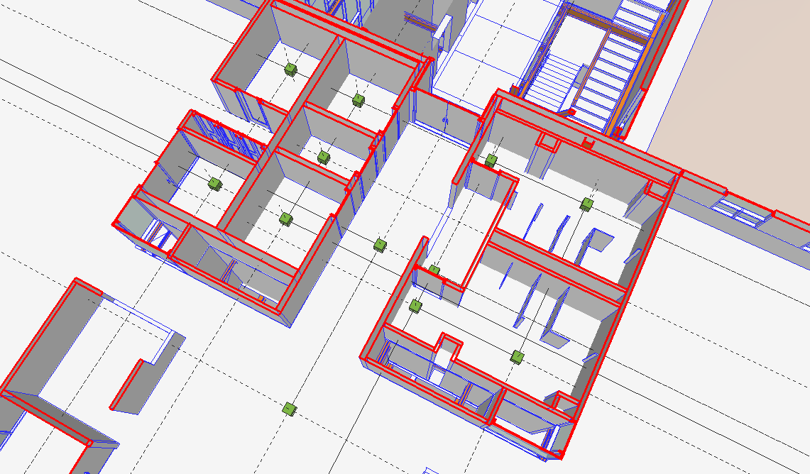
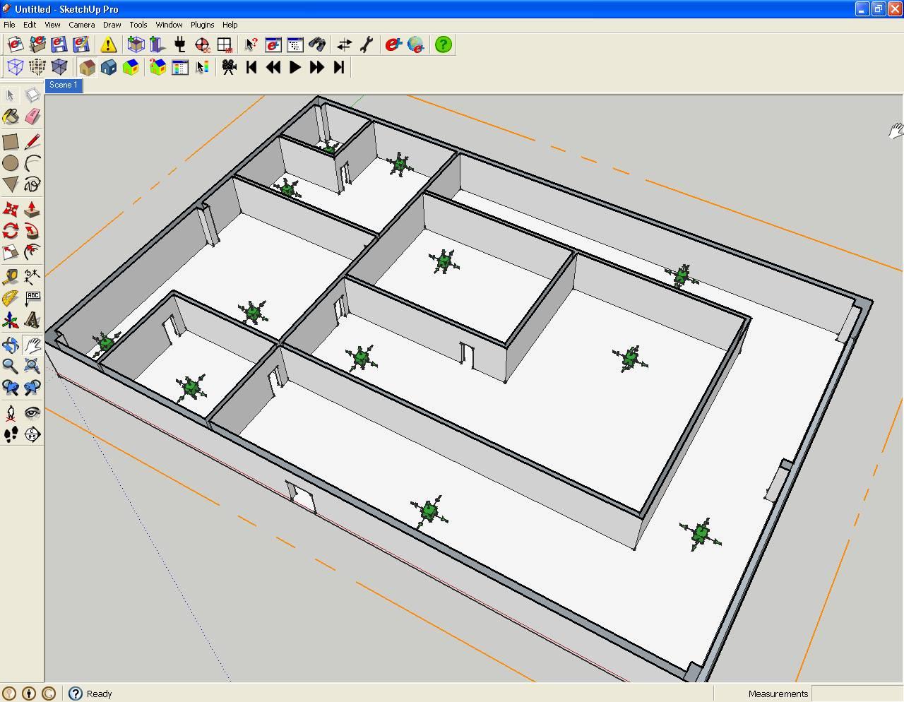
      I have attached a screenshot of a mock with green cubes placed. I can see how all of these guides will become a mess, but maybe I can set them just to show for whatever the active cube is. You can see how the bathrooms get two cubes each to capture the L shape. I didn't care about the stalls or the columns, just basic room shape. each space will become it's own group.

      expanding puck.png

      posted in Developers' Forum
      DavidBoulderD
      DavidBoulder
    • RE: Possible to make Building Elevations aligh to altered axes?

      Related to this if you want a non rotated plan view right click on one of your current axes, and choose align view. Then save that view as a scene to easily jump back to it.

      posted in SketchUp Discussions
      DavidBoulderD
      DavidBoulder
    • RE: Keyboard Shortcuts

      I had thought it would be a nice interface to assign keyboard shortcuts to have a keyboard image that you could just drag tools into vs. the current method. Another thing that would be nice (short of improved GUI to assign keyboard shortcuts) is a plugin that would generate a keyboard shortcut screenshot based on your current settings.

      posted in SketchUp Discussions
      DavidBoulderD
      DavidBoulder
    • RE: Alternatives to YouTube for training Videos

      There is a "Swap Audio" tab, and I thought I could fix some of my narration and re-upload, but "swap audio" just lets you remove your audio and dump in music from a selection that Google has.

      posted in SketchUp Tutorials
      DavidBoulderD
      DavidBoulder
    • Alternatives to YouTube for training Videos

      I'm going to be making a long series of tutorial videos. I'm initially using YouTube for the videos, but one problem I'm running into as that I'm finding the need to make updates to the video or Audio. It seems with YouTube that the only way to accomplish this is to delete the video and upload a new one. I lose the history of the video with this and more importantly the URL, so any links to it would be invalid.

      Am I missing something in YouTube that would allow me to accomplish this? Of course hosting internally is an option, bu I'm looking for external hosting options. Wondering if Vimeo or other solutions offer a workflow to update video and or audio tracks?

      David

      posted in SketchUp Tutorials sketchup
      DavidBoulderD
      DavidBoulder
    • Problem with copy multiple and entity observer

      I've noticed a bug in our OpenStudio plugin. We have an observer to recognize when new entities are made. What I've found is that if I use the move tool to copy a group that is being observed and then use *3 or /3 (any number in place of 3); I end up with an extra copy of my group at the position where I originally copied it.

      Related to this if I use /2 and then /3, I end up with all of the copies made when I did "/2" and all of the copies made when I did "/3". If I do this for non observed objects when I do "/3" right after "/2" the original copies are deleted and then then new ones are made. I think this is the same issue that happens above, the original single copy isn't being deleted before new ones are being made.

      Wonder if anyone has run across this, or has ideas on why it is happening and how to fix it. It is really only an issue for groups as opposed to loose geometry. SketchUp automatically corrects for loose geometry on top of each other.

      Thanks,

      David

      posted in Developers' Forum
      DavidBoulderD
      DavidBoulder
    • RE: Keyboard Shortcuts

      Here is my shortcut set for OpenStudio Plugin. I'm all about grouping common tools together vs. tryign to match the letter of the tool. (Selection tools together, modification tools together, view/camera tools, tools to create new objects)

      OpenStudio-shortcuts.png

      posted in SketchUp Discussions
      DavidBoulderD
      DavidBoulder
    • RE: Orto correction of aerial photographs

      If the aerials were shot with a rectilinear lens (straight lines are straight instead of curved) and if it was pointed directly down then the distance represented by an inch on the edge of the photo would be the same as the distance represented by an inch at the middle. A a square would look like a square anywhere it occurred. If things are skewed or curved, then you need some correction. If you do need correction it is important to get an outcropped photo, or if it was cropped at least know exactly how it was cropped so you can re-create the center of the photo.

      The kind of correction that I think of as being unique to aerial photos, vs. correction for panoramic stitching is ortho correcting for tall buildings, taking the top of a tower that looks like it is outin the street and putting it back directly where it should be. At the same time you recover the missing street element from another aerial and fill in the hole. In an ortho corrected photo you wouldn't see the sides of any buildings, just tops.

      Third page on this PDF shows a before and after aerial
      http://www.sanborn.com/Pdfs/Article_Stand_Straight_Up_2001.pdf

      posted in SketchUp Discussions
      DavidBoulderD
      DavidBoulder
    • RE: Joint Push Pull Classic (Old version) - v2.2a - 26 Apr 17

      I've been playing with Joint Push pull on some relatively simple non orthogonal but simple objects (still just six sided objects). I was surprised to see when I changed my cube to something non orthogonal and then performed a JPP my newly made faces and edges were not parallel to their original elements.

      Reading into the documentation I think that is because Joint Push pull gets the vector for the new point from the average of the three points. This seems perfect on orthogonal objects, or maybe even symmetrically angled objects, but not when asymmetrical angles are introduced. I made an asymmetrically tapered cube and used the standard SketchUp push/pull to extrude the faces out by 24 inches. Based on an earlier test I confirmed that the new Joint Push Pull line is on a vector from the original point through the center of a triangle of the three points generated by the push pull. The distance between the original point and the new point is 2' 8-5/16" (I assume the length is optimized to minimize the change in the position or normal of the three planes). I then used a different method to generate the desired new shape. I drew lines for each pair of faces showing where they would intersect if they had been extended. These lines all meet at a point which represents the ideal location for the new point. It allows the other planes to stay exactly where they should be. 24" away from the original faces (and still parallel). Incidentally the distance between the original and new point with this method is 2' 8'11/16".

      Would it be possible to have an alternate method for JPP that worked in this way. I suppose it may be slower, first have to determine the implied intersection lines for each pair of adjacent faces, and then where they intersect, but I think the results would be very clean. In theory (as long as your push pull distance was not too large to create problems) you could JPP a selection of surfaces in by 24 inches, and then back out by 24 inches with almost perfect alignment (minus rounding errors) to your original geometry. Maybe this won't work in all cases, but for the times it will work it could provide better results. I think it is better for boxy shapes vs. highly faceted surfaces (if making them smaller vs. larger).

      I have attached a close up image of a intersection showing standard SketchUp push/pull and then the new point generated by a JPP operation or and a new point generated by my implied intersection method.


      SketchUp file that screenshot was from. This shows my workflow a bit more.

      posted in Plugins
      DavidBoulderD
      DavidBoulder
    • RE: The "Duh!" thread (aka the Doh! thread)

      Just stumbled across this. Take a 10' cube, use the scale tool to vertically stretch the cube, and just type a distance. This become the new height for your selected object. You don't need to give it a positive or negative number to say home much smaller or bigger you want it. Just type the size you want it to be. If it happens to be smaller than the existing size, then it will get smaller. This seems more useful on a single axis stretch, but it also works when scaling x,y & z at the same time.

      Don't know how many times I had to divide 10'6 3/4" by 9'3" to figure out the proper scale for something. Actually a long time ago I realized I can snap the stretch to a guide or other geometry so I typically drew a dummy line to snap to, but now I don't even need to do that.

      (update), so I guess it was right there in the online help, but I haven't read that in 5 years
      http://sketchup.google.com/support/bin/answer.py?hl=en&answer=94906

      Other nice tidbits. you can type a negative distance to mirror the object, and if you do a non,uniform 2d or 3d scale, you can type multiple distances, to for example make whatever shape you have drawn, fit in a 20',30',50' bounding box.

      posted in SketchUp Discussions
      DavidBoulderD
      DavidBoulder
    • 1
    • 2
    • 3
    • 4
    • 5
    • 6
    • 17
    • 18
    • 4 / 18