sketchucation logo sketchucation
    • Login
    1. Home
    2. billwheaton
    3. Posts
    ℹ️ Licensed Extensions | FredoBatch, ElevationProfile, FredoSketch, LayOps, MatSim and Pic2Shape will require license from Sept 1st More Info
    B
    Offline
    • Profile
    • Following 0
    • Followers 0
    • Topics 2
    • Posts 11
    • Groups 1

    Posts

    Recent Best Controversial
    • RE: SU8 - WISHLIST

      The plugin for Center of Gravity is great, but it's slow and doesn't work well for repeated usage of components.

      The center of mass should be built in, automatic and faster. Right click and choose "point at Centroid" to mark it
      Materials need a density attribute so that you can find out how much an object weighs when painted with it.

      Acceleration due to gravity should be adjustable.

      posted in SketchUp Feature Requests
      B
      billwheaton
    • RE: SU8 - WISHLIST

      Guides/constructions for circles and arcs.
      Arc completion/complement/extend.
      Incorporation of SketchyPhysics or similar
      Allow polygon to be created from the midpoint of a side in addition to the vertex (i.e. inscribed and circumscribed polygons)
      Make all/any sub-window stackable and dockable. Make them pull out in a tray so they don't overlay the tool icons across the top or side.
      Valuable real-estate is lost to the right of the "help" menu choice, make use of it.

      posted in SketchUp Feature Requests
      B
      billwheaton
    • RE: Irregular Crescent shape with lightening holes

      So... I think I have it now.
      here is a picture of it and how it relates (in principle) to what I am doing in case you are curious...
      The octagonal thing holds the 12" diameter telescope mirror.
      rockerbase.jpg

      First, I drew the outline and used the offset tool to draw 1/2" in (on a separate copy)
      I drew the first large hole bottom dead center. then I measured 3 degrees to the left and estimated the center, trial and error. Then I did the same thing on the right for the remaining holes. The crescent attaches to the mirror box with four 5/16" bolts. The box, the crescent and the tine on the far side rotate in altitude about the hole in the tine. The crescent rests on two teflon bearings. The whole thing rotates about the azimuth in the center of the base plate.

      I gotta say, that after making the crescent, (took perhaps 3 hours) the rest of it went together in about 45 minutes from scratch.

      Did I ever mention how much I love Sketchup?

      posted in SketchUp Discussions
      B
      billwheaton
    • RE: Irregular Crescent shape with lightening holes

      @xrok1 said:

      here's an idea you may be able to build on.

      That's actually my first thought. It evenly spaces the holes, or could... but I found out what I really meant, was equal spaces between them. What would be nice would be a tool that draws circles tangent to two curves. Then all I would need to do is move it into position.

      posted in SketchUp Discussions
      B
      billwheaton
    • Irregular Crescent shape with lightening holes

      I have an irregular crescent shaped object used as a rocker trunnion bearing. It is 3/4 inch thick. The outer convex curve is a circular arc of 12" radius and 157 degrees (those are the critical measurements), and the inside concave curve is a nice bezier curve. One horn is tapered more acutely than the other. The greatest thickness of the horn is around 3", but is not too critical.

      The part is made of machined 3/4" sheet aluminum and is intended as a bearing, similar in shape to what you would find on a simple rocking chair. I've attached an attempt.

      I want to make this part light, so I am putting lightening holes in it that are evenly spaced and centered between the inside and outside curves. They are thus functional and pleasing to the eye. The rocker is manually operated and supports no more than forty pounds of weight, so it is light duty. It slides on teflon bearings around the arc's center.

      To draw this, I think I need to find the center line between the two curves and draw the lightening holes centered on it. I am really lost on how to do that with any accuracy. When I do it by eye, the amount of material between a hole and the edges isn't very even. Making the holes evenly spaced is proving a challange too.

      It took me several hours to make the attachment. crescent.skpcrescent.skp The holes have about a 5 degree separation.
      Does anyone have any ideas you could share to make this more accurate and/or easier?
      EDITED to include my screenshot


      crescent.jpg

      posted in SketchUp Discussions sketchup
      B
      billwheaton
    • RE: Noob: Understanding transformation.inverse

      Good example. I was thinking that in a limited way, but didn't fully appreciate the whole scale and rotation effect too. Good to know.
      Hm. Seems like threads aren't hierarchical here.

      posted in Developers' Forum
      B
      billwheaton
    • RE: Noob: Understanding transformation.inverse

      Thanks Martin. And I read those and they were a great help, but I didn't find much there about what the 'inverse' method does. The way ThomThom describes it, it sounds like an "undo" command.

      posted in Developers' Forum
      B
      billwheaton
    • RE: Noob: Understanding transformation.inverse

      Thanks, that's a great help.

      @thomthom said:

      group.transform!(t)

      Then you have moved that by a certain distance.

      If you want to move it back to its original position you can use the inverse transformation.

      group.transform!(t.inverse)

      Ok... so suppose you didn't transform it in the first place what would be inferred by [ruby:1tz432dx]group.transform!(t.inverse) group.transform!(t.inverse) ?

      Because that is what it looks like its doing in the section above. that might be why TIGs got "### put into right place ???" as a comment. I'd have to ask him of course.

      posted in Developers' Forum
      B
      billwheaton
    • Noob: Understanding transformation.inverse

      I'm having trouble understanding what transformion.inverse does as I examine other people's code and try to learn.

      In TIG's CofGravity.rb code there is a snippet for placing a group...

      ### add markers at cog etc
      tgp=entities.add_group(todo)
      cog_gp=tgp.copy
      ...
      ...
      cog_gp_tr=cog_gp.transformation
      ...
      ...
      ### put into right place ???
      cog_gp.transform!(cog_gp_tr.inverse)
      

      I've seen other things like this and people doing it as a matter of course. To me its like the underware gnomes.

      1. first you get a transformation
      2. then ???
      3. then you get its inverse.

      For the life of me, I can't figure out what it does. The help says there are lots of examples on the interwebs, - greaaat.

      Some help that might make it click in my head would be really appreciated.... like "when you have this, and you want that, then run inverse on it" might do the trick.

      Thanks so much!

      posted in Developers' Forum
      B
      billwheaton
    • RE: [Plugin] Center of Gravity

      @unknownuser said:

      This is exactly what I have been looking for I think. I just don't know how to program Ruby well enough, and I'm really unclear on the sketchup API object model. This rocks my whole world and maybe now I can finish that telescope.

      I had such high hopes, but here there are a couple things that make it not work for me as is.

      Here is a very simply example to illustrate the problem, and I am sure that woodworkers would be familiar. I corral parts into assemblies of sub parts and create components from them.
      A side and a rail become a 'side assembly'.
      Two side assemblies, a front, a back, and a bottom and a knob become a 'drawer'.
      Three drawers become a 'drawer set'.
      Two drawer sets, side by side go into a desk carcass.

      Drilling down into a 'side assembly' and selecting the rail part I run CoG.
      Then I select the side part and run its CoG.
      Then I select both CoGs and run their composite CoG, to get CoG of the 'side assembly' system as a whole.
      Because the side assembly is mirrored on the other side of the drawer, it too gets a composite CoG in it.
      But the COG for it is physically on the other side of the drawer.
      Going up a level in the assembly hierarchy is the 'drawer' component I'd like to get the CoG of it. It is the composite of the individual drawer parts.

      the COG of the back
      the COG of the front
      the COG of the bottom
      the COG of the knob
      the COG of the left side (problem here)
      the COG of the right side (problem here too)

      The problem is, the left and right side assemblies don't have their CoG exposed at the same level as the other 4 parts.
      If I use the outliner to drag the left one out of the one instance to the containing instance (the first drawer for example)then it has the correct position for the left side, but then its not part of the component anymore. Opening the right side assembly reveals that it is indeed gone. So before moving anything to the containing instance, I must first make a copy of it for each instance it exists in. Then, I visit each of those instances, select one of them in outliner and move it up a level. That works pretty good. Everything then being at the same level, (drawer) a composite COG for the drawer can be made. But again, once made, if you use more than one drawer (the 'drawer set') then you have to copy the CompCOG object for as many drawers as you have and visit each drawer with outliner and move those up a level in order to make a second level 'drawer set' CompCOG. And likewise for the desk carcass which consists of two of those 'drawer sets'. As you can see, its pretty darned cumbersome, but it works, and its potentially better than I had before with spreadsheets.

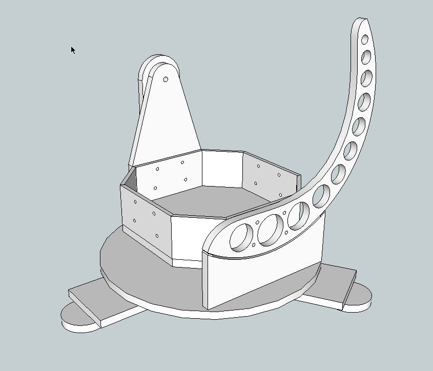
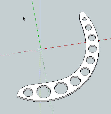
      Of course, finding the CoG of a desk with drawers is trivial because who cares. It's on four legs and it sits stationary in an office. But a telescope is required to be balanced. There are mirror cells, draw tubes, eyepieces, bearings, gimbals, finder rings, finders, prisms, dew heaters, tracking motors, cameras and every imaginable part.

      A warning when you pull something in from a saved component that has one of these CoG elements in it. Sometimes the embedded "CoG" crosshairs get renamed to "CoG#1" and "CoG#2" etc. The code, as it stands ignores them. To make them work, you need to replace them with "CoG" after you reload the saved component... which negates the whole reason for saving components in my estimation... I haven't gotten the hang of all that, especially when it comes to replacing complex components for simplified proxy components to speed up rendering.

      The thing is, I really like Sketchup. It's intuitive, accurate enough for actually building things. I understand how it works out of the box. And every time I go back to TurboCad I feel like I want to take a shower. The learning curve on Autocad and SolidWorks (as if I could ever afford that) is so far beyond my capability If it were my job it would be a different story, but I'm not an architect or mechanical engineer.

      When I have $400 - $4000 to kill, I spend it on tools for my woodshop. I think a lot of other Sketchup users are the same way. Spending $10-#20 on a great script is not a problem though. I drop that kind of dough in a heartbeat down at the home improvement store every week.

      So TIG, if you can figure out my ramblings (sorry, I am like that) I would be willing to donate $20 or more and I would urge others to contribute to make it worth your while too.

      posted in Plugins
      B
      billwheaton
    • RE: [Plugin] Center of Gravity

      I like that a lot. I am making a telescope (12.5" mirror) and balance is very important. The last thing I want to do is add weight to it in order to balance it, because it's already almost too heavy to be portable.

      This is exactly what I have been looking for I think. I just don't know how to program Ruby well enough, and I'm really unclear on the sketchup API object model. This rocks my whole world and maybe now I can finish that telescope.

      Previously I was copying a face, then rotating it to horizontal, then using Centroid.rb to find the centroid, then rotating the centroid and face back the other way and pasting the face back where it came from. Then I placed my centroid component there and moved it half way down the target component.

      Then, in a separate spreadsheet, I put the area of the face times the height of the part times the density of the material to get its weight. Using the 'query tool' I got the xyz coordinates for the spreadsheet.

      I did this for every part and used the resulting moments to find the composite Center of Mass. Let me tell you, it was a pain in the butt and very slow (days). And always with the dread of moving something out of place or adding a new part.

      I think using this will be a lot easier. After all the nested composite Centers of Mass are trickled up to the top component's COG, then all I have to do is to query it to find its XYZ coords.

      A couple of ideas:
      Make the resulting CofG component a Dynamic Component that reports its xyz position, mass, volume etc.
      Is there a way to regen the COG when I modify a component's shape?
      Recursively regen nested composite CoGs when a shape is modified, or when the spacial relationship or density of components changes?
      Create a report of all of them?

      Thinking out loud, I understand that the code takes a while to run, and why. I wonder if there is some sort of mathematical integration trick that wouldn't require slicing it up like that. Polar slices? Integration certainly will work on a cube or a sphere, but that's the hard way of course. But how would you know ahead of time so as to change the method.

      I'm afraid its been too many years out of college to remember any of that.

      EDITED TO ADD THIS:
      But, I have been thinking about the cog of a random solid...
      For every non collinear vertex, if you add a constant weight, and then picking one random vertex calculate vectors to each other vertex. Then average them all. The CofG will lie on a vector's line from the starting vertex. Then pick a second random vertex and do it again. I think that the two lines will actually meet (not be skewed), and the intersection of the two lines should be the centroid of the solid. For a simple convex hull object I think it works, and others like donut or hollow sphere topology I think. But I am way out of my league at this point.

      -billwheaton decaturgausa

      posted in Plugins
      B
      billwheaton
    • 1 / 1