How to make 3d object 'lean' or distort
-
Hello there.
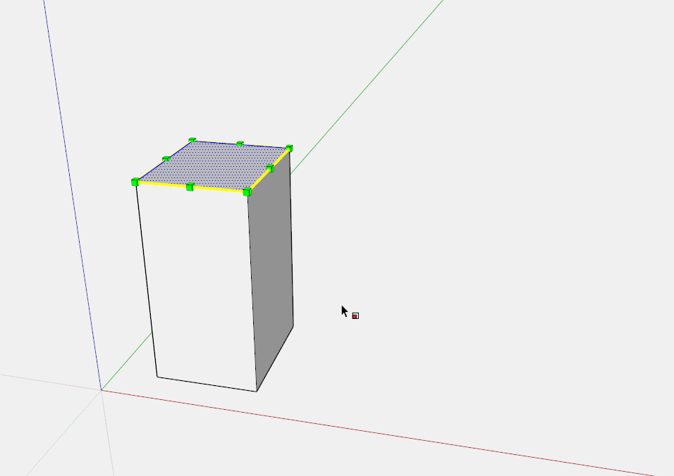
I'm trying to design a component for my motorcycle and after learning the basics (scale, groups, etc.) I can't find a way to make an object 'lean'.
Basically, I want to make the object on the left (imagine it's the end of a brick) lean over but leaving the top and bottom surfaces the original dimensions and changing the dimensions of the sides (and obviously the thickness of the object) to suit the angle of lean:

-
You can move the top geometry (edges, faces, ...) with the move tool to the right (inside the group).
-
As was stated by Cotty, the move tool can be used easily.

-
Click image to play
...or scale if it has thickness
-
What cotty said... also if the object is pretty detailed you might check out the fredoscale plugin.
-
For a more complex object use FredoScale Box Planar Shearing
oops. what Tuna said...
-
I'm curious about what the OP is drawing and wondering if simply move the top over to one side is the best way to draw it.
-
@dave r said:
I'm curious about what the OP is drawing and wondering if simply move the top over to one side is the best way to draw it.
Thank-you all so much for your fabulous help. There are some things that the videos just don't mention.

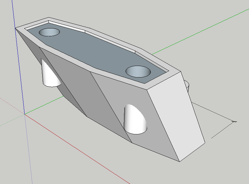
Here's my *.skp but I'm stuck again. The object is a rear-view mirror extension and goes between the fairing and the mirror.
A 'straight' version would of course be easier as only one set of bolts need be used, but I was looking to lower the mirrors a little also. Now I'm stuck trying to make the bolt holes. The top seemed to work OK but I can't seem to select the two circles on the bottom surface any more - even to remove them.Also, I need to make a cut-out at the lower end of each bolt-hole for the nuts to fit.
Can you people point me in the right direction of some tutorials on this kind of process?
Thanks so much again. Cheers. M.
-
You have several problems here. How about if I do a tutorial showing how to put the holes in the riser?
You need hex-shaped recesses in the lower ends of the holes for nuts. Which is the lower end of the hole? Where it comes out the angled side or on the flats? Are they identical top and bottom? How big are the nuts? How much clearance do you need?
What is the on-center distance between the holes? You're using a template with a rather coarse precision setting for the size of the project you're drawing.
-
Check your PMs.
-
@dave r said:
Check your PMs.
I don't seem to have permission to reply to PM's, but thank-you very much for your advice.
I'm working my way through it as we speak but may have trouble with your non-beginner parlance.

Cheers!
-
Now with 3 posts under your belt, you should be able to send PM's feel free to ask for clarification as needed.
-
@dave r said:
feel free to ask for clarification as needed.
Thank-you Dave.
Well.. I spent a few hours trying to figure out what you mean, but unfortunately I was bamboozled right from when you said; "When creating geometry for things such as the holes in this block, I like to work outside the component.", and then followed that up with:
"The hole cutting shapes are drawn in situ". Those two statements to me seem to be polar opposites, but I am a bit thick.I then tried to follow your {edit > cut / paste} instructions but had trouble placing the bolt-hole component. Next thing I know (after much intersection, etc.), it's not a component any more. Don't ask me how I managed that, but the attached will give you an exact idea of what I'm after. I'd like to do the same with all four holes, and if what I have done thus far is any indication, it will take me about another three days.

As you can see, I have changed the axes to help me align the 6s nut shape (which I made separately and plonked on top of the circular hole).
Anyway.. I think I'd do better to put this on hold and spend another couple of weeks learning wtf I'm doing and then come back to it.
Thanks for all your help.. I'm sure it will become clear the more tutorials I do.
Cheers.
-
I replied via PM.
Hello! It looks like you're interested in this conversation, but you don't have an account yet.
Getting fed up of having to scroll through the same posts each visit? When you register for an account, you'll always come back to exactly where you were before, and choose to be notified of new replies (either via email, or push notification). You'll also be able to save bookmarks and upvote posts to show your appreciation to other community members.
With your input, this post could be even better 💗
Register Login


Advertisement