3D Truss Models
-
Call me crazy but I want to build something like this on my 10 acres so I can see all the way to the beach.
Given my wind speed (155mph ult.) and seismic zone (D2) I am probably looking at some serious holdowns at the first level (HDU 11). I would have to run the numbers but it would probably work. I would probably also sheath it with 5/8" plywood inside and out for some serious shearwall action, at least on the the first two floors. I would probably also frame the first two floor with DF No.2 2x8 studs or 2x6 studs at 12" o/c. I'm thinking spiral staircases between levels to save as much floor space as possible and to make it more interesting. Minimal windows on the first three levels and then the top level would have a lot of windows for the view. 11-7/8 TJI 210 for the floors with 3/4 sheathing T&G, 16" o/c.
The structure is 16'x16' with grade to top plate height of 38'8".
The roof is 6:12 pyramid hip with 2x8 rafters, I may go with a steeper pitch though.
On a structure like this overturning is a serious threat, I would need to check the dead weight of the structure and see if the seismic or wind forces could potentially lift the foundation right out of the ground. The solution is to increase the dead weight of the structure especially at the base, by upsizing the footing and stemwall. You will notice my stemwall is 10" thick, 36" deep and a 24"x12" footing, even this may not be enough.
Anyone design something goofy like this before. I don't know if my county building dept. would give it an approval though even if its engineered (stamped).
-
Since I have now have roof cladding enabled I figured it only made sense to have some sort of wall cladding enabled for the gable end walls:
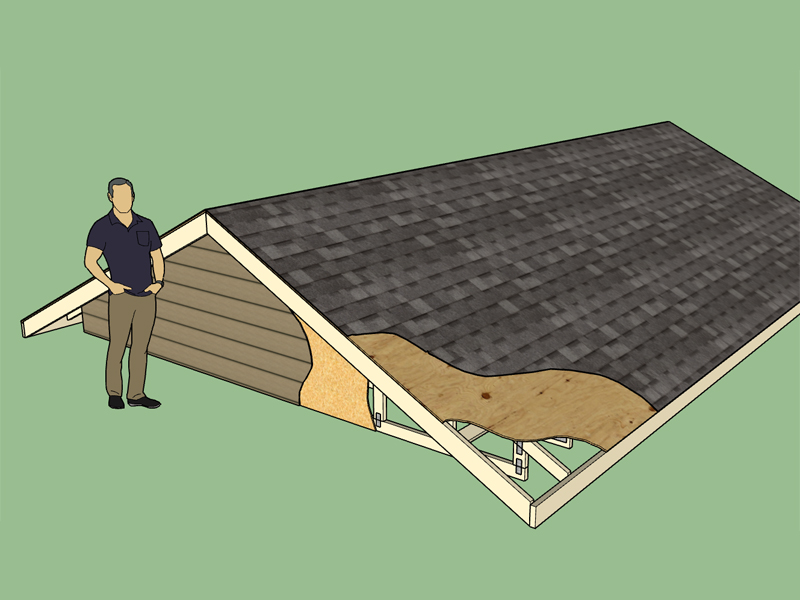
The advanced options now allow one to specify wall cladding, the settings can be adjusted in the "sheathing" tab of the global settings. I currently only have 4 different colors of Hardiplank Siding but I will add more as requested and I can find textures that I like or create. It should also be noted that it isn't too hard to swap out the texture for the user's custom textures.
I'm also thinking about adding an option for an air gap between the wall sheathing and the wall cladding in the case that someone wants to use brick as their cladding option. For standard veneer brick in the US the air gap is usually 1" if my recollection is correct.
I will try to roll these latest additions into a new revision here shortly.
-
Version 1.8.1 - 01.29.2017
- Enabled gable wall cladding for common trusses.
- Added four "HARDIPLANK Cedarmill" siding colors into the wall cladding material library.
- Enabled sheathing and cladding for valley truss sets.
-
Here is a simple structure created with the Truss and Foundation Plugins along with Housebuilder:
I like Housebuilder but I really feel like I need to develop my own Wall Plugin since it will tie in better with my Truss Plugin and allow the user to create the different sheathing and cladding options on the same layers.
Creation of the foundation and roof both took less than 30 seconds to create. The walls, windows and doors did require manual editing. I also realized that it would be useful to allow the option for wrapping the floor framing in wall sheathing and cladding so that this can be unioned with the appropriate sheathing and cladding on the walls above. I will add this into the Todo list.
-
So far I have not really had the opportunity to use my own plugin on a real job, other than some minor conceptual structural models.
Last night I had the opportunity to model a garage/office as part of a real world study for a building design.
This further re-emphasized how much I need to put together my own Wall Plugin, something I might seriously wade into this weekend.
View model here:
3D Warehouse
3D Warehouse is a website of searchable, pre-made 3D models that works seamlessly with SketchUp.
(3dwarehouse.sketchup.com)
Its 25Mb because of the vehicles I inserted from the 3D Warehouse, it would be nice to have more lightweight test vehicles to use as space fillers and sizers, does anyone have any suggestions?
-
Medeek,
Plugin in is coming along!
Is polygon slabs available?Thanks for your dedication to a unique plugin.
-
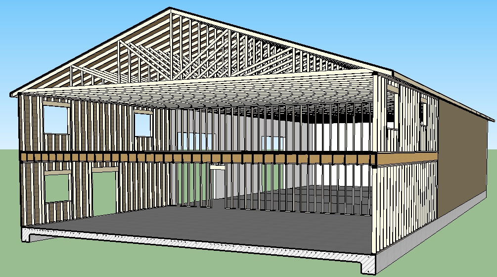
The 18.5' highbay/garage only needs to be 16' in height and the 2nd floor of the office space needs 9 ft ceilings:
3D Warehouse
3D Warehouse is a website of searchable, pre-made 3D models that works seamlessly with SketchUp.
(3dwarehouse.sketchup.com)
Note the valley truss set, and how I was able to easily tie these two roofs together. For simple roof lines I'm pretty happy with what the plugin can do.
-
When combining different roofs on complex structures I often find myself having to delete the outlookers, overhang and gable end truss on one end of the roof assembly. Then today I had a request from a user to enable the ability to limit the gable geometry to only one end. Based on this I will try to set up another option for the gable end truss option which allows for only the creation of one side with the gable end geometry. This means I will have to rework some of the advanced options to make sure it is compatible but I think I can make it happen fairly quickly.
-
I've just downloaded the trial version and started playing with it. I've been following the development process all along, and I'm impressed with what you've accomplished.
A couple of questions:
- Is there a specific reason why you've chosen to generate geometry as groups and not components?
It would seem to me — especially on complex models — that it would have a significant effect on file size. But more importantly, any manual changes required would propagate to all instances.
-
Do you have a timeline on when Gable walls will be enabled for attic trusses?
-
Would it be difficult to enable an option for floor/open joist truss as the bottom chord on attic trusses?
It would form a sort of attic bent that can extend the open span width — without having to place a support beam below. (we're looking at this option for our current project).
- Any thoughts of coding eyebrow dormers? I realize that combination of coding complexity and rare demand for this style probably places it low on the priority list, if not off it entirely... but never hurts to ask!
I'm also really looking forward to your proposed framing plugin and seeing it develop as well. The design/build firm that I do most of my work for specializes in Passive House construction, so we would have different requirements for wall assembly types from most. If you're interested, I would be happy to provide our requirements / input on sample wall assemblies.
Thanks for all your effort in building a very comprehensive and useful tool.
Doug
-
I've just downloaded the trial version and started playing with it. I've been following the development process all along, and I'm impressed with what you've accomplished.
A couple of questions:
- Is there a specific reason why you've chosen to generate geometry as groups and not components?
It would seem to me — especially on complex models — that it would have a significant effect on file size. But more importantly, any manual changes required would propagate to all instances.
Some items such as the overall roof assembly I've created as a Group simply because it is not likely that this entire assembly will need to be replicated over and over in a model. I've tried to use components wherever I've see duplication so as you suggest one can easily modify one instance and all instance will be updated. There are a few place where I probably need to change from groups to components, such as roof outlookers, I will look into that one.- Do you have a timeline on when Gable walls will be enabled for attic trusses?
This one should not be too big of a deal to complete. I put it on the back burner since no one was bugging me about it. Basically with the plugin my Todo list is so vast that I simply go after the items that people are bugging me the loudest for. The sqeaky wheel get the grease...- Would it be difficult to enable an option for floor/open joist truss as the bottom chord on attic trusses?
I can easily code it, what I need though, are some good shop drawings of this type of configuration so that I am comfortable with how this is typically put together. I probably worry to much about getting it right but with my trusses I like to know that they are close to what you will be getting from your local truss plant as possible. Send me some shop drawings, preferably "Mitek" of what you have in mind.It would form a sort of attic bent that can extend the open span width — without having to place a support beam below. (we're looking at this option for our current project).
- Any thoughts of coding eyebrow dormers? I realize that combination of coding complexity and rare demand for this style probably places it low on the priority list, if not off it entirely... but never hurts to ask!
I don't even know how to properly frame these. Send me some drawing or models of what you would like to see and I can probably make it work, I just need some education in this regard.I'm also really looking forward to your proposed framing plugin and seeing it develop as well. The design/build firm that I do most of my work for specializes in Passive House construction, so we would have different requirements for wall assembly types from most. If you're interested, I would be happy to provide our requirements / input on sample wall assemblies.
I would like to start with the most conventional wall types first since this will have the broadest appeal, however I would be interested in learning about passive house construction and how this differs from standard construction. Most everything around here is 2x6 studs on 16" centers with R-19 or R-21 insulation, 7/16" OSB exterior sheathing and 1/2" or 5/8" gypsum wall board on the interior. The wall cladding is usually hardiplank siding however I'm not a huge fan of the product since it is quite brittle and tends to break easily when hit by an errant baseball etc...Thanks for all your effort in building a very comprehensive and useful tool.
Doug
-
Thanks for your answers. I'm in the juice on a project at the moment, but when I have some time next week I'll put together some info to send you.
Not sure if I can get shop drawings for the attic truss, but I'll see if my builder can put a sketch together. He's also an engineering by training, so he shares your fastidiousness on structural details.
I've also asked him to draw the eyebrow dormer, since I've never modeled one (well, I've started started on one), let alone framed it.
I understand your approach for the framing plugin — of course you need to start with what is in highest demand.
Thanks again,
Doug
-
In response to a recent request about gable ends of the roof assembly I have created an additional option in the "Gable End Trusses" option when creating common trusses. The new "Front" option only creates the gable end truss and gable end geometry on one side of the truss assembly and leaves the other side open as shown below:
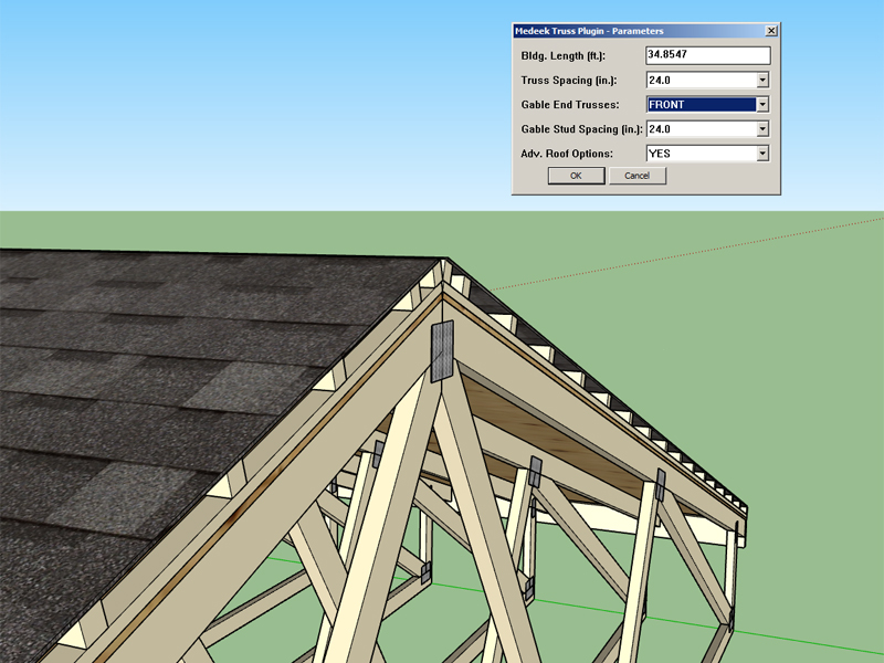
This should come in handy when creating roof assemblies that butt up against walls and other complex configurations (ie. T-shaped buildings requiring Valley Sets etc...)
I've also been slowly working away at bringing all of the common truss types up to speed. The Modified Qeen Truss (Mod Queen) now has plates, raised heels, structural outlookers, layers and materials:
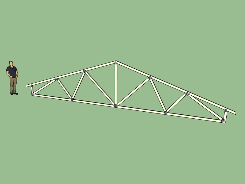
Most of the non-common truss types still need me to go through and integrate plates, layers, raised heels and materials, the amount of work needing to be done is staggering. This plugin is far from a polished, finished product, even after more than a year's worth of time and effort.
-
You've done an immense amount of work on this, thank you for the dedication. Would it not be wise to rather bring all of the truss types on par with each other (feature wise) before venturing into further features and development?
-
I agree. I will probably spend the next few weeks making sure plates, materials, layers, raised heels, one gable only feature and other issues are resolved for all truss types and rafter roof types.
After that I would like to finish up the hip sets, timber truss, and flat truss modules.
-
I'm quite familiar with all of the industry names for various configurations of roof trusses (ie. Fink, Howe, Mod Queen, King Post, Queen Post, Double Fink etc...) What distinguishes these trusses from each other is the configuration of the webs of the truss which is dictated by the number of panels of the top chords and bottom chords. For example the Howe truss is four top chord panels and four bottom chord panels (4/4). Most diagrams show up to a Triple Howe truss (8/8). What is not typically shown is an (8/6) and (8/7) truss, is there any reason for this? These two configurations seem perfectly valid to me, I would call them a Triple Queen and Fan Fink truss respectively. Has anyone come across either of these two configurations?
-
Actually I would change the name of the Fan Fink to Double Fan.
The next size up would be:
Quad Fan 10/5
Double Mod Fan 10/6
Triple Fan 10/7
Quad Queen 10/8
Quad Fink 10/9
Quad Howe 10/10As the number of panels increase in the top chord the number of potential variations increases. So for a four panel top chord truss the number of variations is three, the general pattern is:
(2/x) truss = 1 possible configuration
(4/x) truss = 3 possible configurations
(6/x) truss = 4 possible configurations
(8/x) truss = 5 possible configurations
(10/x) truss = 6 possible configurations
(12/x) truss = 7 possible configurations
... -
My naming convention for the 12/x series of common trusses.
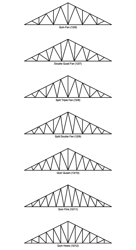
Trusses sure are beautiful things.
-
The common fan truss now has raised heels, plates, materials and layers:
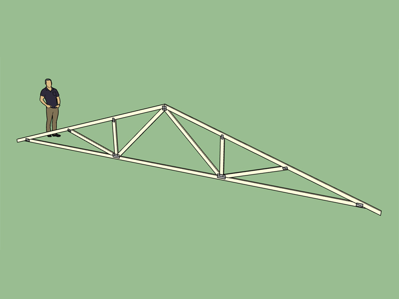
I apologize for the slow progress. I've had some 12 hour work days last week so I didn't have much left in the tank once I got home, usually just eat and then went straight to bed.
-
I've been thinking about stub trusses, is there any need for those?
-
I originally made the roof pitch a drop down box/option since most people use standard roof pitches with their roofs (ie. 4:12, 7:12, 9.5:12 etc...) However, the problem with that is it does not allow one to enter in values other than those provided in the drop down list. The alternative would be to make this a simple text field where the user specifies the roof pitch however my thinking was having the drop down list was more convenient. For the metric templates (when the plugin switches to metric mode) the pitch is given in degrees rather than the customary US pitch (x/12) method, and there is no drop down list, the user just enters in the degrees.
I guess what I should do is add an option into the global settings which allows one to toggle between the drop down list or a simple text field for the pitch input, for the imperial units template.
Advertisement


