3D Truss Models
-
I think a lot more people fab their own trusses than we realize. I don't disapprove but I do think that quality control is imperative. One bad joint in a truss can cause the entire truss to fail which in turn may cause a catastrophic failure of the roof system.
Some jurisdiction will require an engineer's stamp on any site built trusses, as they should, but there are many situations (ie. agri structures, small buildings) where there is no oversite by a building official or engineer. For those situations it would be useful to have an easy to use truss calculator that even the lay person could utilize and understand.
From my side there is some risk and liability associated with this, especially since I have no way to confirm the workmanship of the construction. If someone were to utilize my calculator and design a truss with plywood gussets, and assuming that they built it per the calculations and input the correct snow loads etc... but the construction was shoddy and it failed would I still be liable? Probably so. That is why I have hesitated on releasing the wood gusset portion of my Truss Designer (web based).
-
I think I've beaten the flat truss to death but I noticed after perusing through a number of flat truss shop drawings that the modified warren is also a popular web configuration. Its not too big of a deal to enable this configuration. The flat truss will then have the option between a pratt or mod warren web configuration.

-
Medeek,
The following is not a criticism but a reflection of the difficulty of managing priorities.I think the following article may apply at this stage to your development of the Truss Plugin:
Following article is from:
https://www.briantracy.com/blog/personal-success/how-to-use-the-80-20-rule-pareto-principle/And yes it applies to all of us!

*The 80 20 Rule Explained
Personal Success 80/20 Rule
The 80 20 rule is one of the most helpful concepts for life and time management.Also known as the Pareto Principle, this rule suggests that 20 percent of your activities will account for 80 percent of your results.
This being the case, you should change the way you set goals forever.
What Is The 80 20 Rule?
As I just mentioned, the 80 20 rule is also called the “Pareto Principle.” It was named after it’s founder, the Italian economist Vilfredo Pareto, back in 1895. He noticed that people in society seemed to divide naturally into what he called the “vital few,” or the top 20 percent in terms of money and influence, and the “trivial many,” or the bottom 80 percent.
Later, he discovered that virtually all economic activity was subject to this principle, in that 80 percent of the wealth of Italy during that time was controlled by 20 percent of the population.
We can take Pareto’s 80 20 rule and apply it to almost any situation.
In particular, we can apply it to goal setting and productivity.
Download my 14-Step Goal-Setting Guide to put the 80 20 Rule into action!
How Does It Work?
If you have a list of ten items to accomplish, two of those items will turn out to be worth more than the other eight items put together.
The sad fact is that most people procrastinate on the top 10 or 20 percent of items that are the most valuable and important, the “vital few,” and busy themselves instead with the least important 80 percent, the “trivial many,” that contribute very little to their success.
How To Apply The 80 20 Rule To Goal Setting
Here’s what you should do in order to effectively apply the 80/20 rule to goal setting and to your overall productivity.
First, take a piece of paper and write down ten goals. Then ask yourself: If you could only accomplish one of the goals on that list today, which one goal would have the greatest positive impact on your life?
Then pick the second most important goal. What you’ll find is, after you complete this exercise, you will have determined the most important 20 percent of your goals that will help you more than anything else.
You should continue to work at those goals that you’ve chosen as the most valuable all the time.
Eat The Biggest Frog First
You often see people who appear to be busy all day long but seem to accomplish very little. This is almost always because they are busy working on tasks that are of low value while they are procrastinating on the one or two activities that could make a real difference to their companies and to their careers.
The most valuable tasks you can do each day are often the hardest and most complex, but the payoff and rewards for completing them can be tremendous.
Before you begin work, always ask yourself, “Is this task in the top 20 percent of my activities or in the bottom 80 percent?”
The rule for this is: resist the temptation to clear up small things first.
If you choose to start your day working on low-value tasks, you will soon develop the habit of always starting and working on low-value tasks.
Always Work Towards Your Main Goal
Finally, I want to tell you about a study that has just been done about the attitudes of rich people versus poor people in regard to goal setting. What they found is that 85% of rich people have one big goal that they work on all the time.
So, if you want to be wealthy, do what wealthy people do. Pick one big goal and work on it all the time, and if you do, it will change your life*
-
Enabled mod warren webs for the double pitched flat truss configuration:
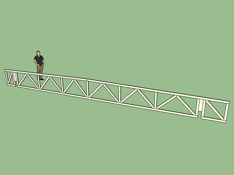
The truss shown above is an asymmetric double pitched top chord bearing flat truss with a mod warren web configuration and cantilever ends. That is quite a mouthful.
I have not added the top chord bearing option and the mod warren webs to the other flat truss configurations yet (flat, monopitch, pitched), however I will if specifically requested.
As Facer has duly noted priorities are critical and there a much hotter items on the plate.
The stepdown hip truss set is the big one, that is next, and yes it will be a game changer.
The flat truss was just a primer to warm up my programming chops, its been almost a month since I was able to touch the truss plugin.
-
Since about version 1.6.0 I've been tracking every installation of the plugin. The funny thing is that I see more installations of previous versions of the plugin than I do of the current version. I am wondering why that is and also where the previous version is being distributed from. It's not a huge deal but it does have me wondering.
-
That is a sign of a software being worthwhile, it gets pirated (unfortunately). Maybe chat to some of the other devs (ThomThom / Whaat / etc.) about how they go about curbing this scourge.
-
I don't know that its a sign of hacking as much as people not having access to the most recent version of the plugin. Possibly two reasons:
1.) The user downloads a version of the plugin and then installs it months later.
2.) Other websites are redistributing the plugin (older versions).I don't provide links to previous versions on my website since the latest version is always better than the last, so again this doesn't make much sense to me.
-
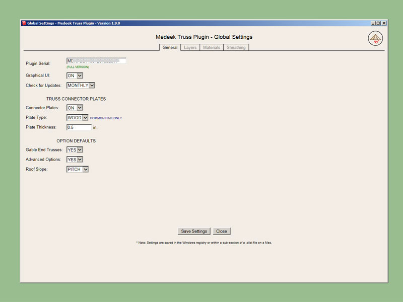
In the global settings I've added a setting to switch between metal and wood connector plates. Initially I will only enable wood plates for some of the more typical common trusses (ie. fink, howe, queen and king), if this feature proves to be popular I may enable it for more truss types.
-
Version 1.9.1 - 06.09.2017
- Added plywood gusset plates for common fink trusses.
- Enabled a "WOOD" plate type option in the global settings.
*Note that the wood gussets are currently only available for the Fink truss, if anyone needs them enabled for a different truss please let me know.
View model here:
-
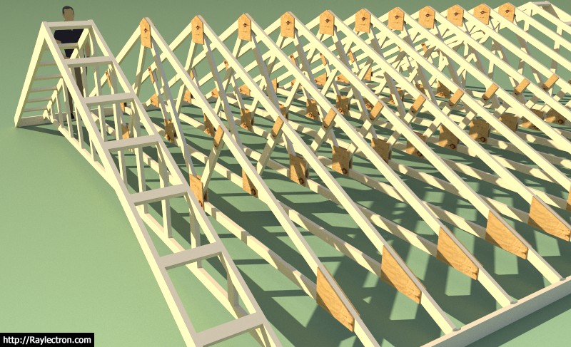
Added plywood gusset plates for raised heel common fink trusses.
View model here:
https://3dwarehouse.sketchup.com/model/b21431bc-c3b6-4038-a81e-f27fc78f69b1/WGC-Truss
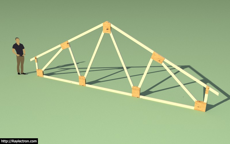
Note that there are currently no calcs associated with these WGC trusses. If you are going to build your own trusses I would strongly suggest you find a local structural engineer to assist in specifying the plates sizes and fasteners, especially if the truss span is greater than 16 feet and your snow loads are greater than 25 psf in your region.
When I engineer WGC trusses I will also call out a waterproof glue as well however I don't take the glue's strength into the calculations. This provides another margin of safety and also the rigidity of a glued and nailed gusset plated truss is superior in my opinion to your typical MPC truss.
Every member is critical in a truss, however some are more stressed than others. Your top and bottom chords should never be anything less than a No. 2 DF. I would suggest No. 1, No. 1 & Btr. or Select Structural. The webs of a typical truss are usually stressed quite a bit less than the chords and sometimes you can get away with stud grade lumber but I would suggest DF No. 2 on all webs as well. A strategically placed knot can easily ruin an entire truss.
Just as important as the materials is the level of care taken in cutting the members and assembling the truss. All joints should fit tightly together so that members in compression can bear directly on their adjacent members. Also realize that tension members may experience load reversals in high wind or seismic events so even tension members are no exception to the rule.
The correct fasteners and fastener size is critical. The nails will be in single or double shear and the joint connection is relying entirely on this shear strength of the fasteners to hold together. Fasteners too close to the edge or ends of a member are not as effective, so fastener placement is also critical.
I am curious how the two truss types would compare in a burn test, which one would stay intact longer. My suspicion is that the plywood gussets would char and slowly burn however the metal plates would heat up and loose their strength quickly and fail.
I know most people don't do this but I would personally stress test each truss before installing it on the intended structure. Mostly what you are looking for is a uniform deflection across all the trusses so that they can load balance properly. If a truss is defective this test should help ferret out this data even though visually the truss may look acceptable.
-
Just for the record the algorithm to size and position the mid top chord to web plate (Plate 2) is a real piece of work:
gamma2 = 3.14159265358979 * 0.5 - @Phi
length2 = @Pldim2 * 0.5 -1
p3x = @Swx4 + length2 * (cos(@Theta2) / cos(gamma2 - @Theta2))
p3y = @Swy4 - length2 * (sin(@Theta2) / cos(gamma2 - @Theta2))
p2x = p3x - (@Tcd + length2) * cos(gamma2)
p2y = p3y + (@Tcd + length2) * sin(gamma2)
p1x = p2x - @Pldim2 * cos(@Phi)
p1y = p2y - @Pldim2 * sin(@Phi)
length4 = sqrt((@Strx4 - p1x)*(@Strx4 - p1x) + (@Stry4 - p1y)*(@Stry4 - p1y))
zeta2 = atan((p1y - @Stry4)/(@Strx4 - p1x))
length3 = length4 * sin(zeta2 + @Theta3) / sin(3.14159265358979 * 0.5 + @Phi - @Theta3)
p4x = p1x + length3 * cos(gamma2)
p4y = p1y - length3 * sin(gamma2)

if @Theta2 > gamma2
  p2x = p3x - ((@Tcd + length2) / (cos(@Theta2 - gamma2))) * cos(@Theta2)
  p2y = p3y + ((@Tcd + length2) / (cos(@Theta2 - gamma2))) * sin(@Theta2)
end
Actually had to use the Sine Law: https://en.wikipedia.org/wiki/Law_of_sines
Its funny because my 15 year old daughter just covered trigonometry in her math class and she told me she would never use this stuff so why learn it.
-
Nice additions to the plugin. Impressive work too. I guess you have engineering training but what else has helped you tackle these programming problems?
Peter
-
There is really very little engineering going on in this plugin, at least for now. Most of it is boolean algebra (conditional statements and a few loops) and a lot of geometry most of which can be solved with simple trigonometry. In a few cases I have to implement an iterative solution so convergence is sometimes an issue. The rest of it is simply manipulating the SketchUp API so that it produces the correct output, that is my Achilles heel.
-
I may have opened Pandora's box with the addition of the WGC fink trusses. I've now had a couple of requests for cut list associated with these trusses. I don't think it would be that hard to generate an html output using SVG showing the various members and their dimensions. This can then be printed to a PDF document by the user.
Any thoughts on creating construction drawings this way. I am essentially bypassing SketchUp's Layout with an Html/SVG solution but perhaps there is a better way.
-
If you're going that route be 100% sure the engineering is correct.
Personally, I think that is going tò far for general use, but may be fine for an engineering version.
-
It's definitely not on top of the todo list but it is interesting how quickly there was a response and request for a cut list of construction drawings.
I agree if I'm to take it this far I will probably want to make sure the engineering is bullet proof, so the short answer for now is that it is probably not going to happen in the near future.
-
I've had a request for an option that makes it so the plugin only draws the top and bottom chords and not the webs. I guess I could see a reason for this in some situations. I'm just wondering if there are any others who would be interested in this option.
-
I've been thinking about site built trusses some more and trying to apply some rational thought to how best to nail together a WGC truss. If you consider nails in single shear, 8d nails spaced at 4" between fasteners with a row spacing of 1" and and end spacing of 1.5" you end up with something like this.
Those are 8d common nails so they aren't very big but spaced at 2" between nails in a row I would be afraid of splitting that bottom chord.
Looking at this I'm fairly convinced that going with longer nails that are in double shear and clinched give more bang for the buck, allow less nails and thereby less chance of splitting the truss members. Thoughts?
-
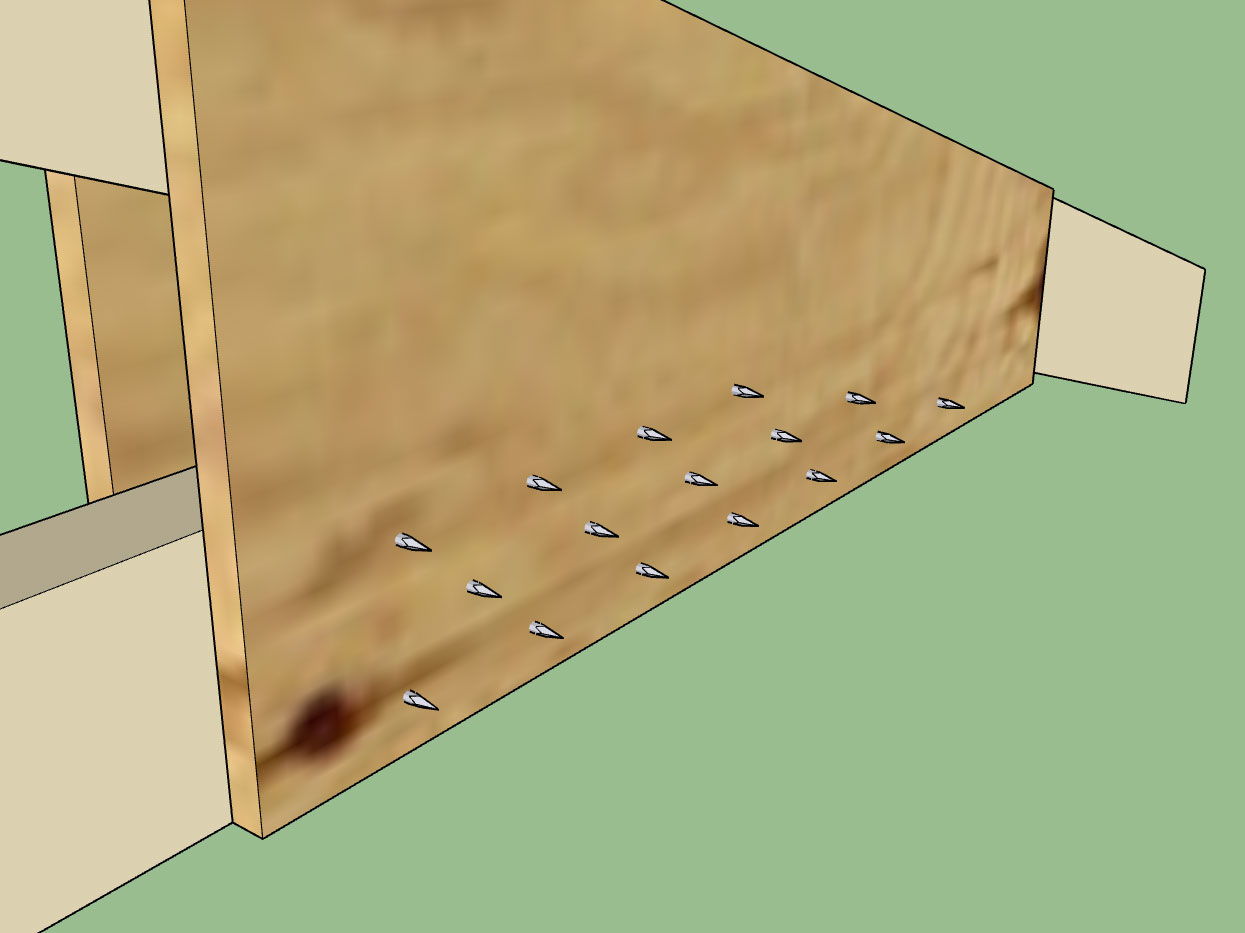
Nailing from both sides is not reasonable in my opinion, there is no way to line up the nails easily from one side to the other, better to just nail from one side which bring me back to nails in double shear.
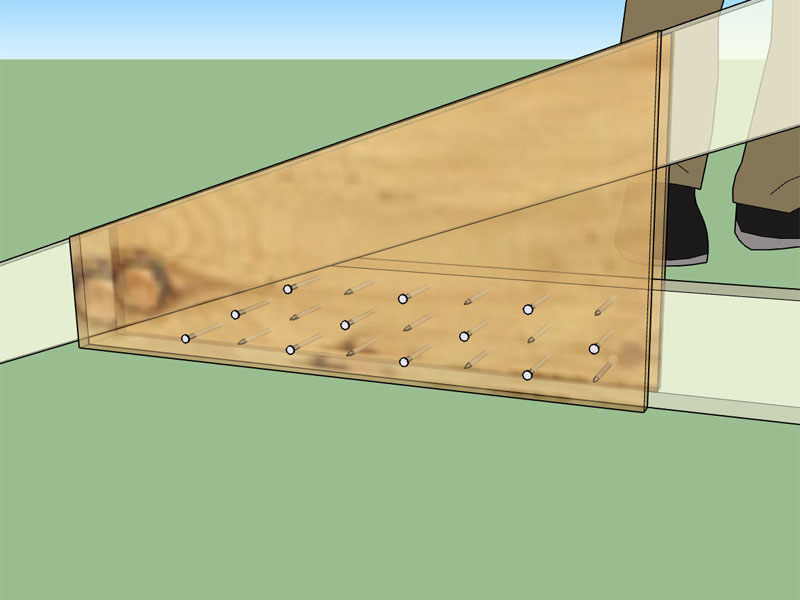
Using a 10d common nail (.148 x 3) and with 1/2" of protruding nail to clinch I get this layout:
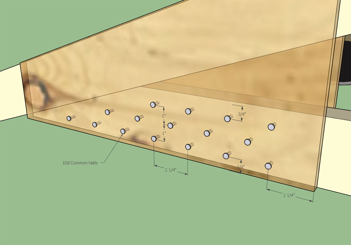
with the backside looking something like this:
I probably don't need a 2.25" end distance (15D) on the plate edge toward the inside of the truss but I am using Table C11.1.6.6 from the NDS Commentary (NDS 2012).
-
If you compare the capacity of a single shear and double shear connection in most cases you get double the capacity, see results for a 10D nail into DF and Structural 1 Plywood below:
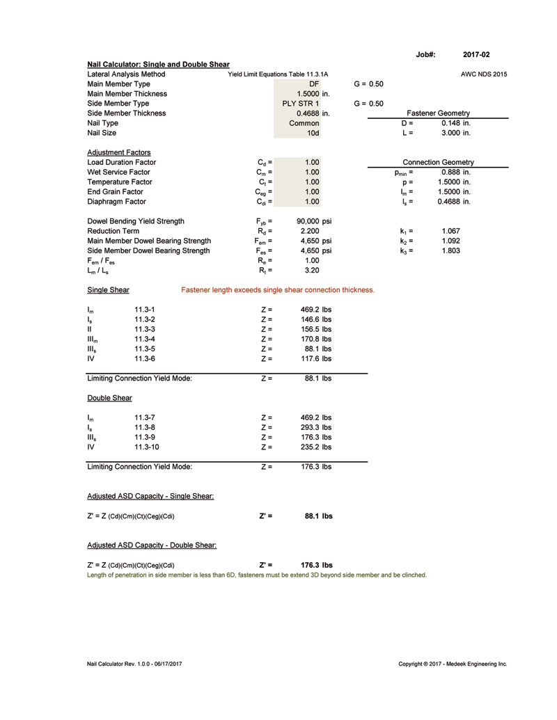
So returning to our previous example we now have 2180.9lbs/176.3lbs = 12.4 => 13 fasteners in double shear, rather than 25 fasteners in single shear, a much more reasonable number of fasteners
Hello! It looks like you're interested in this conversation, but you don't have an account yet.
Getting fed up of having to scroll through the same posts each visit? When you register for an account, you'll always come back to exactly where you were before, and choose to be notified of new replies (either via email, or push notification). You'll also be able to save bookmarks and upvote posts to show your appreciation to other community members.
With your input, this post could be even better 💗
Register Login


Advertisement