[Plugin][$] TopoShaper - v2.7a - 01 Apr 24
-
I just checked Ruby console but there was nothing. I will PM the model.
-
@miikka1978 said:
I just checked Ruby console but there was nothing. I will PM the model.
I answered the PM.
The problem is due to an artificial rectangular hull which you includes in the terrain. This prevents to calculate the correct concave hull and therefore the zone of influence of contours.Fredo
PS: By the way, your model is quite complex, but apparently Toposhaper could deal with it
-
 Hello Fredo
Love your script!
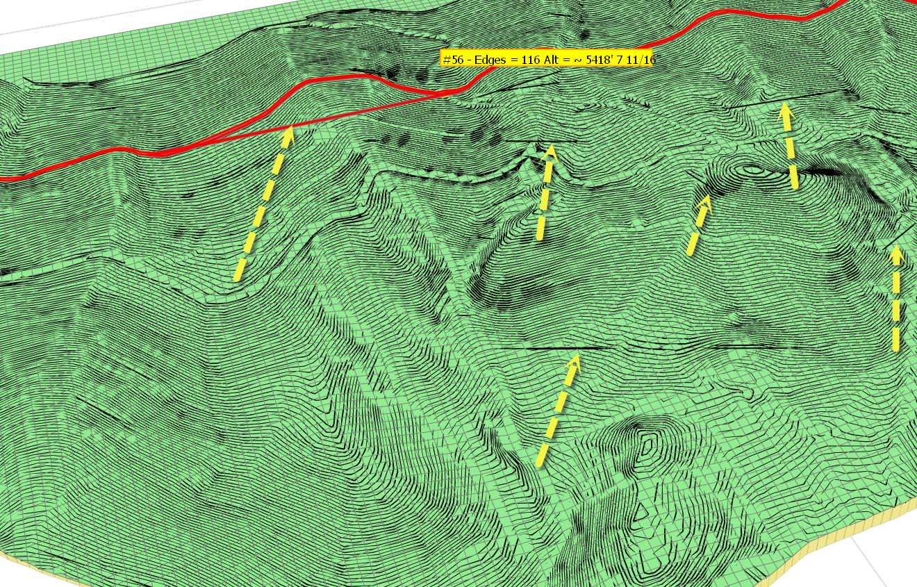
Can't tell you how long I have hoped for something like this.I am having a problem with a large topo map I am working on.
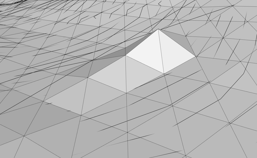
As illustrated in the attached image, when I go to preview created mesh there are lines that do not correlate with my topo set.
When I generate the mesh, i get this type of deviation.
Can you suggest what might be going wrong?
many thanks in advance.
Best.
Bob Pineo
-
Fredo,
Thought it would be helpful if you had topos in case you wanted to run script yourself.
Here is a link to Dropbox.
https://www.dropbox.com/s/0brplieftg8p27v/just%20raw%20mesh%20for%20TIG.skpBest.
BP -
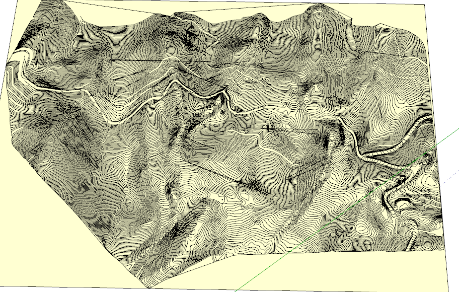
Your contour map is extremely large, with close to 30,000 edges, 750 contours, 400 automatic junctions, but also extremely dense, since contours are separated by a very small distance.
It's a miracle that TopoShaper (and Ruby underneath) can do something with it!
There are a number of problems that I detected:
-
do not simplify the contours. There are only 12 simplified, but the contour map is so dense that the simplification creates overlaps with adjacent contours.
-
watch out some automatic junctions at the periphery. Some are overlapping.
-
there seems to be a bug in Toposhaper, because I observe some shadow straight contours in the Preview mode (but not in the Cleanser mode). I keep your model and will have a closer look at it. It may be related to the calculation of the Concave hull.
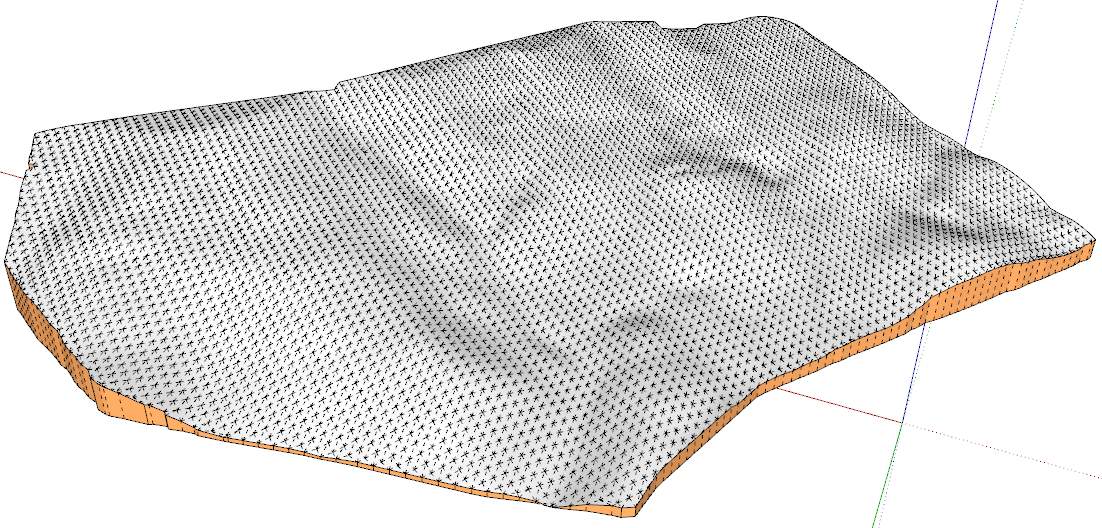
I run the generation with a 100 x 69 and obtained a result which is not too bad. But with the density of the contours, I think that the sampling should be over 300 x 200 to exploit the high definition of the contours.
I can't tell you what to do exactly to avoid some of the artefacts you may observe, except maybe to remove some contours and try again.
Fredo
-
-
Thanks Fredo.
Yes you are right, this was a dense a map, but I thought I would get as high a resolution as possible because I thought the denser mesh would provide finer resolution for up close shots.
The way I solved the problems showing up when I ran the plugin was to open the sketchup file twice, and arrange each one on my split screens. I ran Topo Shaper on one file, and where I noticed a particular problem on one of the contours I would spend some time on it figuring out what was going on.
In some cases there was an odd remnant that had to be removed, in other case I just deleted that entire line.
in the end, and once the problems where identified and fixed the mesh was created without any trouble.
Thanks so much for this plugin, its been wonderful.
Best.
BP -
The Chinese version by GUANJIN is too bad ,and lots of Chinese friends ask me to translate the TOPOSHAPER in Chinese again.It spends me a lot of energy and time.This one must be the best Chinese version.Enjoy it!Thank You!
Here is a contrast:LY's and GUANJIN's.

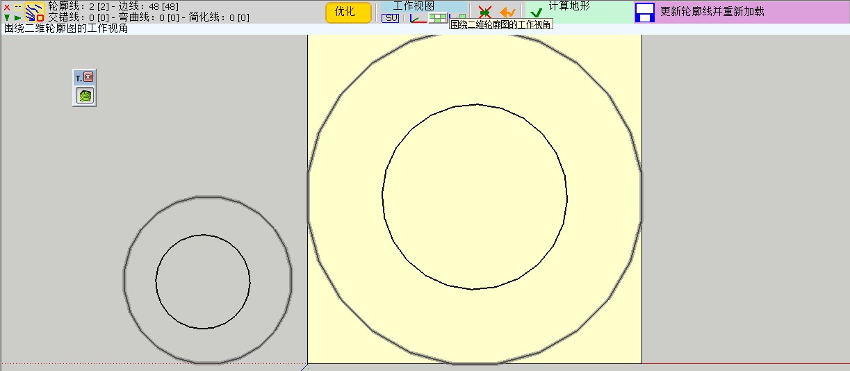
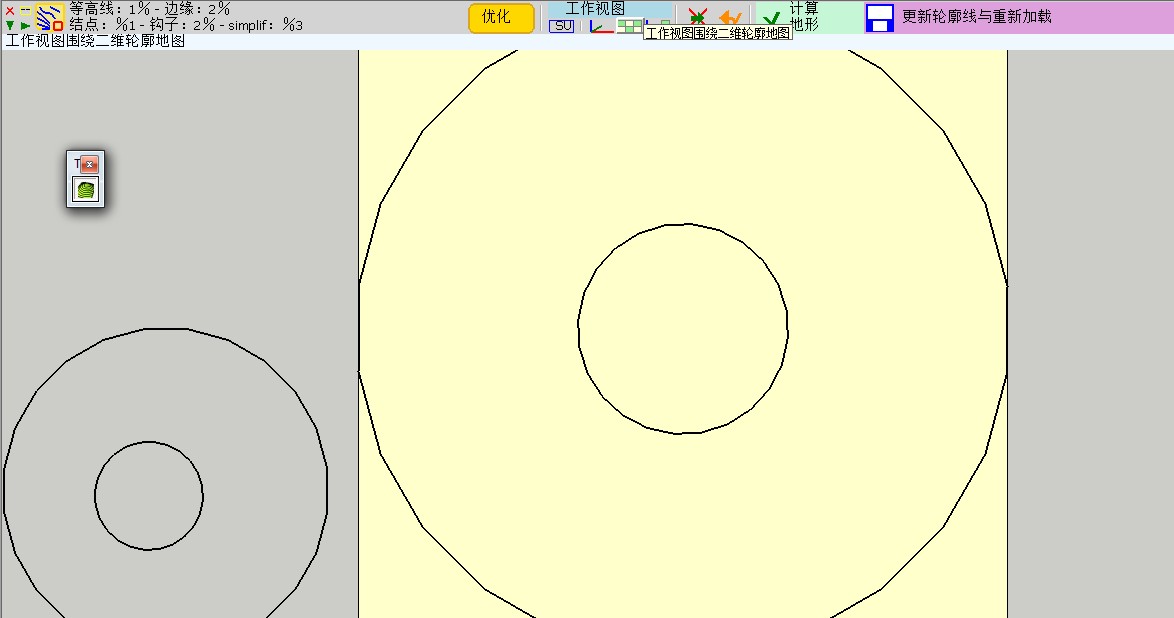
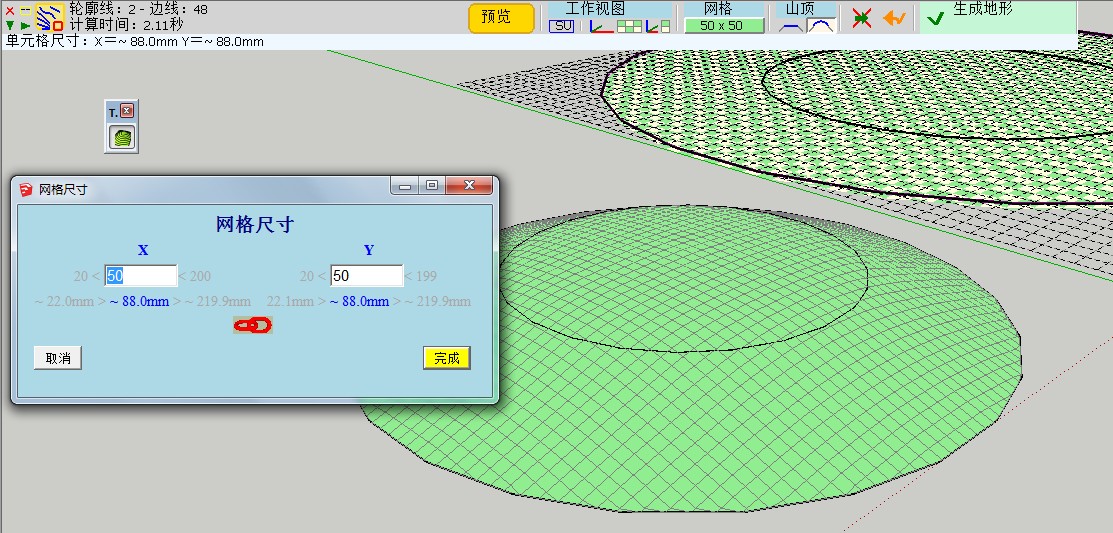
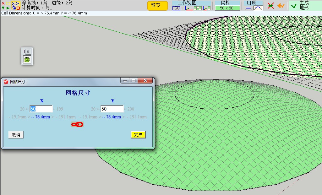
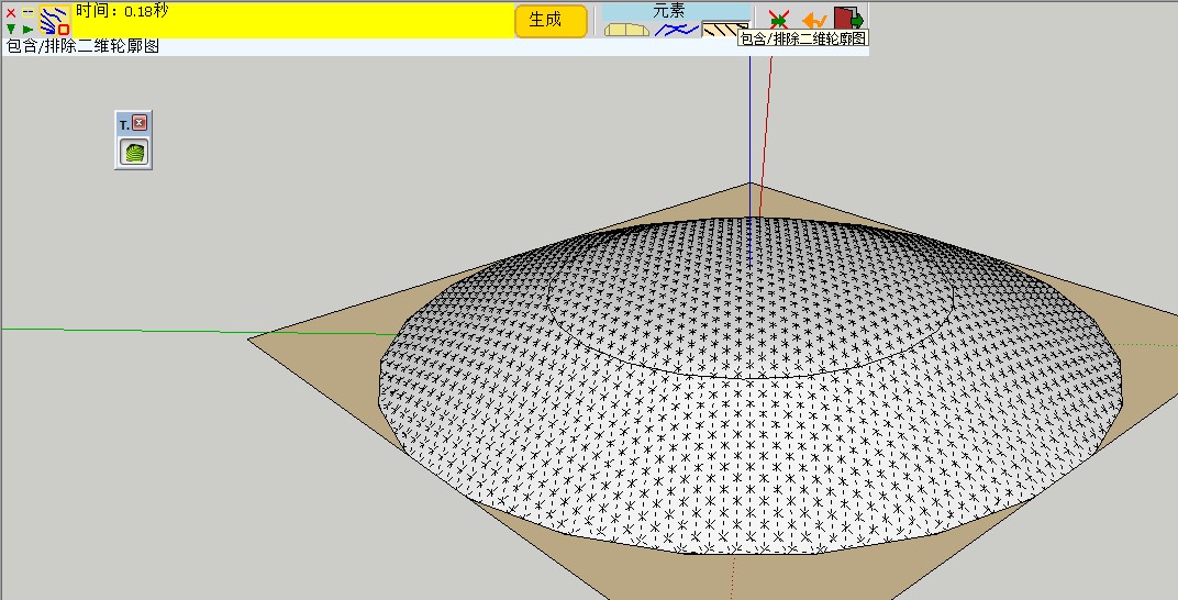
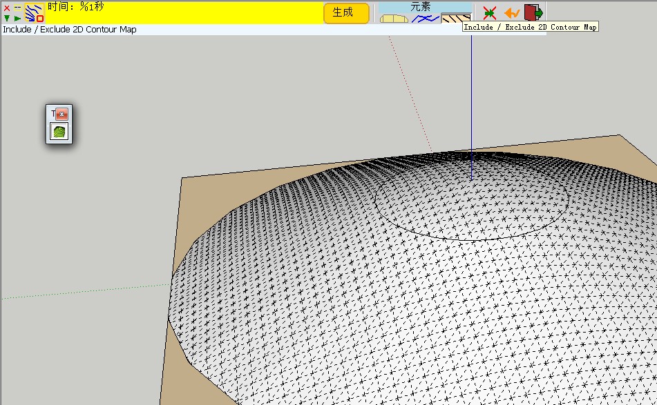
You will find the truth.
SketchUpBAR LY871108 -
Bob,
Glad to see that you finally found some workarounds.
My experience with the few contour maps I have been using for testing is that the resolution of the contours should always be put in perspective of the required mesh definition. Toposhaper is based on interpolation, which means that intermediate contours below the resolution of the mesh won't really be useful. In the case of your terrain, I think you needed a resolution above 300 x 200 to exploit all the details of your contours.
I still think there are some bugs left in TopoShaper and your contour map will be useful for me to track them (and hopefully fix them in a next release).
Fredo
-
Thanks so much Fredo.
Best.
BP -
Hi,
Thanks for this plugin, really helps a lot.
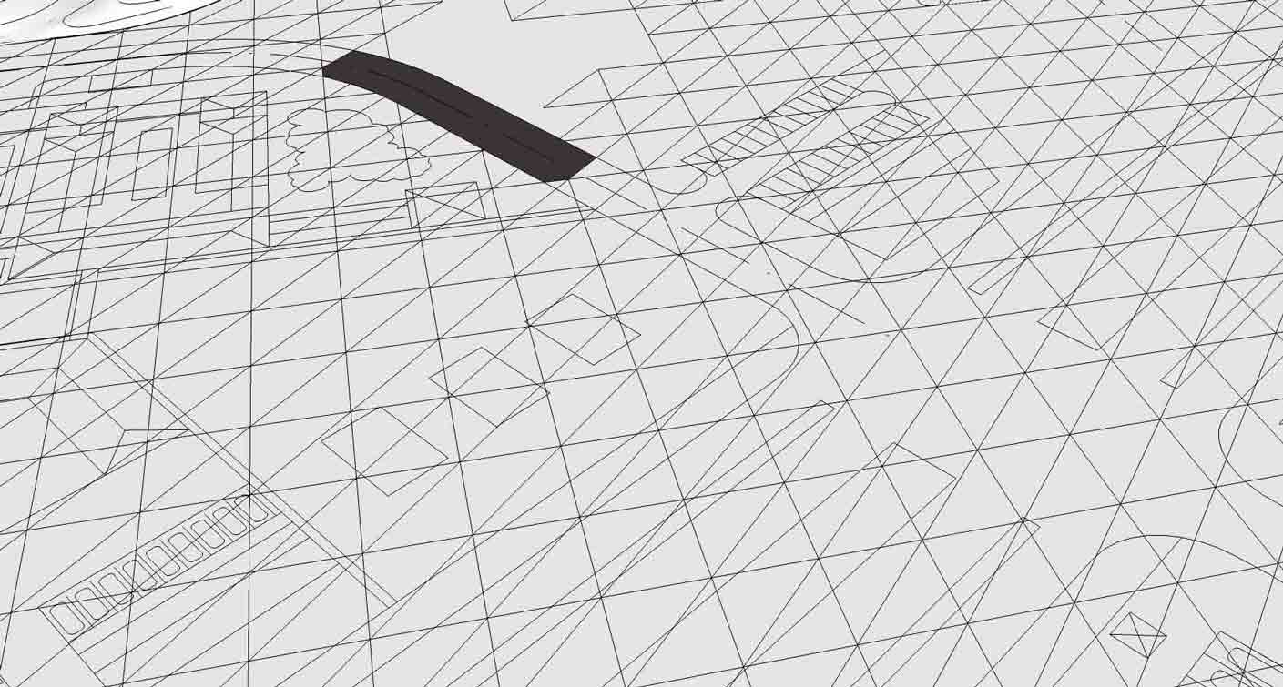
I was trying to do some landscape design and used toposhaper to make faces in my cad underlay, but all triangles did get unsmoothed. Is there any way how to prevent that ?
-
I guess you just need to select the terrain as a group and then soften / smooth it via the SU dialog box.
Fredo
-
hi,
i am sorry my question wasn't precise enough. I want to all triangulated edges to be smoothened, but i want to keep my drawing edges visible. And i want to be able to select surfaces and read the area of streets gardens etc.
If i use your suggestion all edges will be smoothened.
Is there any setting that can do that or some workaround ?thank you for this great plug in
D.
-
Not sure what you did but the native (well, SandBox IS a plugin) SU way would be to create the terrain surface and then drape (Sandbox tools) your line work onto it. That way the line work will show as edges on a smoothed terrain.
-
Brief description what i did.
import dwg (mostly in one plane)
run toposhaperwhat i hoped for = have a surface generate over dwg lines with separate surfaces for different parts of dwg. Like street, lawns, pavements would be one surface with selectable areas.
-
I tried this and I got a flat surface with soften-smoothed triangulation--separate from the import.
This is not what toposhaper is developed for, but you could at that point "drape" the dwg lines onto it if you want with SandBox. Within the limitations of dwg import (often has problems) and the software (can't solve everything) you may get what you want.
I would recommend: 1. Remove all lines you really don't need in a terrain model before import. 2. Separate buildings and things that are not going to be molded with the terrain into groups before import and possibly group roads and landscape areas. 3. Clean up the dwg after you get it in. Intersections of curves for example will not be correct. You may wish to make faces in the dwg before going further.
Then use the Sandbox tools to make a terrain and drape the lines onto it. Alternately there are ways to just apply a terrain grid in specified areas like lawns. I'd try it with simpler shapes first. The whole dwg import may be too much for it.
My methodology would be to separate graded or sculpted terrain completely from buildings and most hardscape--merging or cutting only where it's useful.
-
thanks i will look into it.
-
good
-
 Very, very thank you. Fredo. You are the master!!!
 -
To anyone that can help and guide me on this.
Attached is a grading plan of a piece of land that I am working with. I imported this from a 2d dwg file. I made a group of the contours and when I run the plugin I can't get it to show any grade variations and there are some extra lines that show up in red.
I don't follow why some lines are green and others are not.
The large flat open area is where I am placing a building and parking lot.
Just not sure how to go about this.
This file is saved as V8 but I am working in 2013Pro.
Thanks,
Larry
-
cubcrafter - many of the lines have gaps in them (double click any line and normally you'd get the entire line; not the case with many of your lines) - get thee to http://www.smustard.com/script/StrayLines and you'll find a free tool to help you find them. Then you can join them manually by adding lines to the gaps, it's worth running this on any imported ACAD (or any dxf or dwg file) import.
OR this (US20.00) plugin helps you close them http://www.smustard.com/script/CloseOpens - well worth the money I'd say.
Here's a discussion on the issue http://sketchucation.com/forums/viewtopic.php?f=15&t=24427&p=211465&hilit=lines+joined+gaps#p211465
Advertisement


