How do you detail a bezier curve?
-
Hello all, can you help me...
I have used a bezier curve in my drawing and need to put some kind of dimension onto it to tell construction how to make it.
SU curves i use chris fullmer's arc to centre point to find the radius. with bezier curves this can't be done. theres lots of radii.....
what do you guys do in this situation?
how can i draw it so they can understand the curve .......is there some architectural way....cheers in advance
chris -
Maybe you can draw first Circles and arcs-circles
Then draw / snap on them the beziers curves by Fredo 6 ?
Then edit if necessary with Edit Bezier tools -
If the guys 'are on site' and they are going to set it out 'by hand', then a lot of complex trig and so on will not endear you to them!
An arc/circle is easy to do as the center/radius is easy to specify and then to replicate with a pin and a length of string,
So is an ellipse, with its two foci locations and a 'loop of string' based on the axes [it's a simple calculation for a sting loop of its major_axis*3 I think - but I haven't done it for ages].
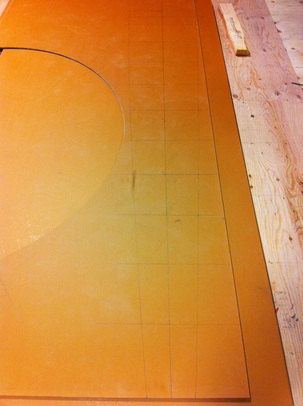
But a curve like a Bezier is so complex and varied - ever changing radii etc, so can I suggest you set out an XY grid and give them the dimensions to the intersections of every intersection with the curve.
Or explode a copy of the curve 'off to the side' and add base-line dimensions [X&Y] it to every 'vertex' set-off from a pair of XY axes datum...Of course if they are 'manufacturing' it, then a DXF will let it be CNC cut etc... and you are sorted...
-
do what TIG is saying.. plot the points then connect with a batten of some sort..
i'll put up a better example once i get to my laptop but for now...
-
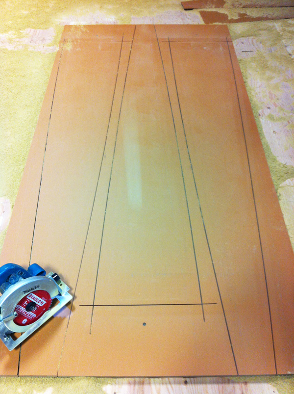
another way to do it without going the CNC route is to print the curve full size on a large format roll printer (if you have access to one and if the curve will fit on it's width)...
use a spray adhesive to temporarily glue the paper to the stock.. cut through the paper/stock in one go.. remove the paper..
-
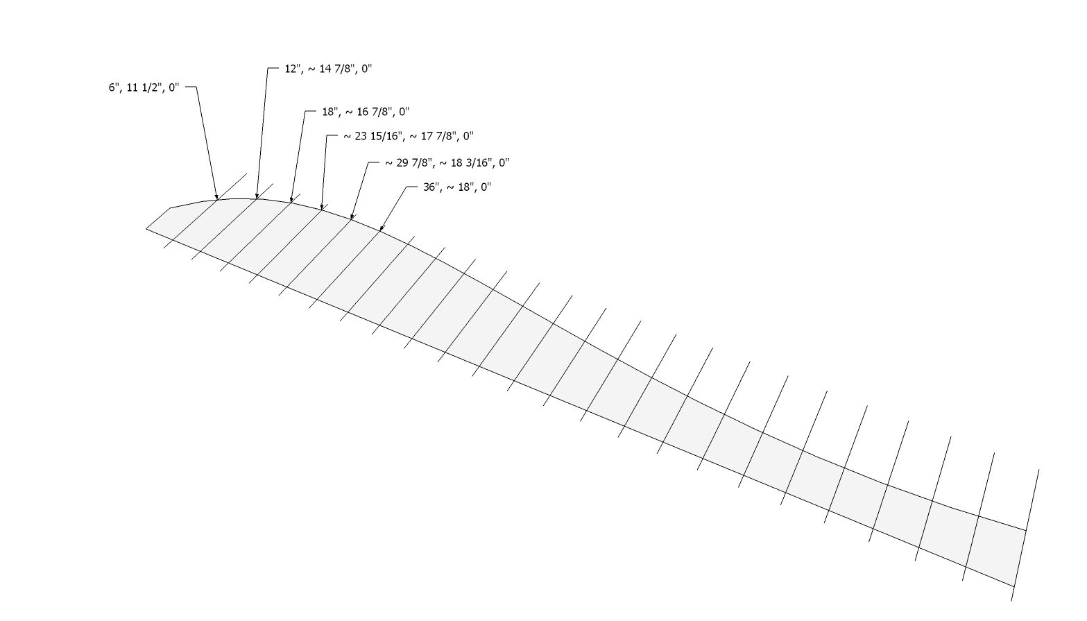
You might also create a table of offsets similar to the method used for boat building. Distances from a datum line are given at regular intervals (stations) along the curve. Those points are laid out and a flexible batten is sprung around them to get the curve. You can get the numbers off the model by using leader text at the intersections like so:
In boat building the table looks something like this.

The line labeled 'Sheer' in the lower half of the table gives the distance from the datum line (centerline of the hull) for the top edge of the hull. Boat builders working in imperial units use the format shown in the table. The sheer at station 1 shows 1-6-7 which would be read 1 foot, 6-7/8 inches. In lofting the lines from the offsets, the points would be marked from the table and the batten sprung round them. Since the offsets are rounded, minor adjustments would be made to points that don't hit the batten.
Maybe more info than you want but the point is, you can make the table and round off the offsets a little when the curve is laid out, the batten will help to correct any round errors.
-
It's basically 'back to basics'. Thank you guys this has been most informative. I understand then there is no set way to do this but it is do-able.
Cheers.
Hello! It looks like you're interested in this conversation, but you don't have an account yet.
Getting fed up of having to scroll through the same posts each visit? When you register for an account, you'll always come back to exactly where you were before, and choose to be notified of new replies (either via email, or push notification). You'll also be able to save bookmarks and upvote posts to show your appreciation to other community members.
With your input, this post could be even better 💗
Register Login


Advertisement