GRID DISTORTION
-
@infinity said:
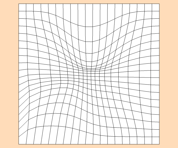
Here is a picture of what I would like to do as well as the piece of art work.
So do you think that thomthoms vertex tool plugin will achieve this.
I was thinking that I could export it as a 2D dxf file to my CAM software.
weird.. i can't really figure out if that thing is perspective dependent or not.. but i'm leaning towards it is..
(as in, you have to stand at the same vantage point as the photo was shot from in order to get the full effect)if that's the case, i don't really know what you should do.. besides experiment..
do a few smaller scale tests comprising of forming a grid then moving vertices around manually using the move tool (with nothing selected, click the move tool on one of the grid intersections and move it around)..
figure out what needs to happen first.. then you'll be able to figure out if vertex tools is the right tool..(or hey.. generally a helpful bunch around here.. maybe someone will figure it out for you
 )
)
personally, i'm about to switch back to work mode so i don't have the time/energy right now... -
Thanks Jeff, I really appreciate your input on this
-
-
For some reason only the first version works for me?
-
How did you create this gilles?
I have the sandbox tools and can do the same as you did with the black and white squares one but I dont know how to get a top view to show all the distorted lines.
Thanks
-
A little video
http://www.screencast.com/t/yt9gej2g
Also read this if you want to try this plugin:
http://sketchucation.com/forums/viewtopic.php?f=323&t=6029&start=300#p454588 -
Thanks for the video.
I have downloaded the plugin and pasted it into the plugins folder but it does not appear. Is there something else I should be doing?
-
It appears in context menu: right click on a group-->FFD...
-
The plugin won't appear in plugin window.
Right-click on a group and find FFD in the context menu.
Carefully read the original thread, it is not a so easy plugin as you don't see deformation in real time.
So, save before use and practice a lot.
It may be easier to draw this thing by hand with Fredo6 bezier tools if you want to reproduce the exact thing your picture shows.
Up to you to choose. Good luck and fun -
i'm kinda thinking there are two different things going on in the thread.. the tree example is different than the examples i posted..
meaning, the grid work ala vasarely is meant to be viewed as a 2D piece more or less from straight on..
the tree is more of an optical illusion thing though.. (and maybe it's arguable that the paintings are also optical illusions but the tree thing is more gag like.. the punchline or hook or whatever is being shown to you precisely so youre not left wondering or interpreting the piece yourself.. it's main purpose is to leave the viewer visually disoriented in a realm not so different than that of a magician.. you know?)
anyway... it seems as if the way to do the tree drawing is sort of a combination of what gilles and dave both showed earlier..
draw the thing in 3D.. something like the sanbox method which was shown.. then align a plane in such a way that when the object is draped, it will look like the 3D version except it's flat.. something like what dave was showing..
set up a scene so you can continue to return to the same perspective..
something like that
-
OK Jeff I have made one using the sandbox tools and I have tried draping it on to another plane. This is where I am coming unstuck. I don't seem to be able to align a plane that it will appear to be 3D when its looked from above.
Any chance of an example please if you have the time?
Thanks
-
Think about the physics of what you want to accomplish. The illusion will really only work from one vantage point. Figure out where you want that to be and determine the angle between your 3D mesh and the viewer. Use that angle, or actually its compliment, as the angle between the mesh and the plane onto which you'll project the image.
-
I recall writing a short script to 'project' objects' outlines onto the floor-plane for this kind of thing ? ........ http://sketchucation.com/forums/viewtopic.php?p=320466#p320466
-
Wow TIG thats a really good plugin.
I have now produced a distorted grid and have exported it as a dxf into my CAM software.
There are a lot of open vectors which I can join most of them by using the 'join' tool in the CAM software. There are still open vectors and when I further try to join these, the lines become broken.
Is there a way that I might be able to export this file so my CNC router will be able to cut single lines in the grid both vertically and horizontally?
-
Some screen-shots, and an example SKP file [perhaps simplified?] might help..
-
-
@infinity said:
Is there a way that I might be able to export this file so my CNC router will be able to cut single lines in the grid both vertically and horizontally?
I don't know your software so i don't know if this will help but...
maybe go to top view then window select all the lines in one direction then delete leaving you with only the lines in the Y direction.. recurve/curvizard/weld the lines then group them.. do the same thing for the lines in the other direction.. you can now try to feed the cnc the non intersecting lines..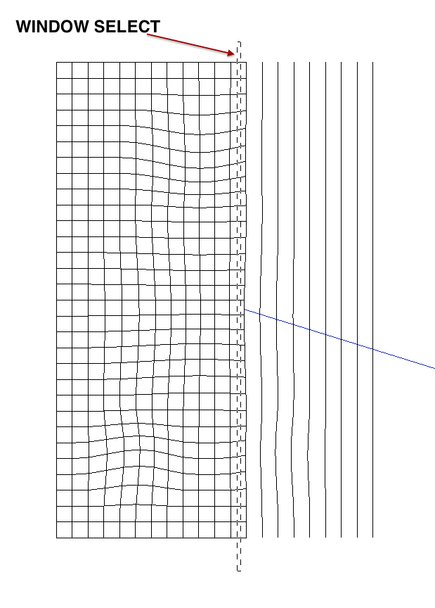
another problem might be that the angles between various segments are too severe for the software to recognize it as a single curve.. if that's the case you might have to use a plugin such as curvizard or BezierSpline which can smoothen out the lines and make the angles less severe (ie- add more segments)..
not sure though..
(and not much time to give more thorough examples.. sorry) -
Thanks for that Jeff.
I have downloaded the weld plugin but I don't seem to be able to weld the segments of the lines together for some reason.
I did separate the lines into parallel and horizontal sets and exported the two sets into my CAM software. I joined the vectors in both sets and will have a go at routing them and let you know the outcome.
Thanks again for you help.
Hello! It looks like you're interested in this conversation, but you don't have an account yet.
Getting fed up of having to scroll through the same posts each visit? When you register for an account, you'll always come back to exactly where you were before, and choose to be notified of new replies (either via email, or push notification). You'll also be able to save bookmarks and upvote posts to show your appreciation to other community members.
With your input, this post could be even better 💗
Register Login


Advertisement