Arc deforming ???
-
@brookefox said:
I'm glad you guys know what you are talking about without being aided by pics.
Such would relax the brain into complacency,
or ease it into insight.
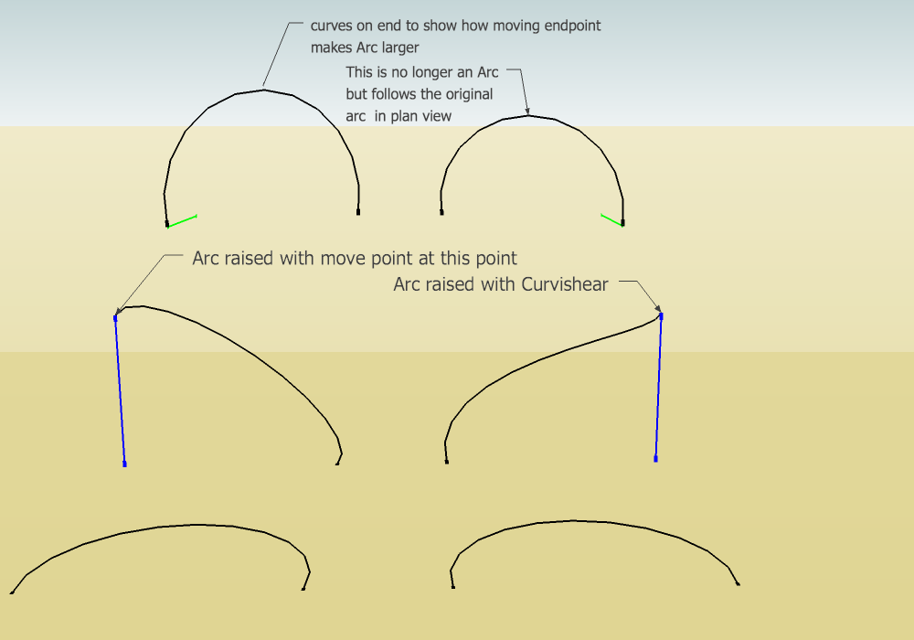
Does this image help? This was talked about in another thread. What is right may be a matter of opinion. The curve with the endpoint moved up is still an arc.
-
Thanks very much, Peter. Very helpful to me. I will come back on the morrow.
Why is the arc with the moved endpoint (row 1 col 2)(which is no longer an arc) no longer an arc? And to be thick, some are no longer arcs, others are (and this is the point?)?
Row 1 col 2 doesn't really follow original in plan, does it, because right the end has been moved (or was that a false horizon?)?
-
@brookefox said:
Thanks very much, Peter. Very helpful to me. I will come back on the morrow.
Why is the arc with the moved endpoint (row 1 col 2)(which is no longer an arc) no longer an arc? And to be thick, some are no longer arcs, others are (and this is the point?)?
The bottom row is the identical arcs lying on the ground plane. The other rows are two views of the two curves:Row two is perspective view of the transformed curves. Top row is the same curves rotated (Note the reference line is green) to see how they look from above.
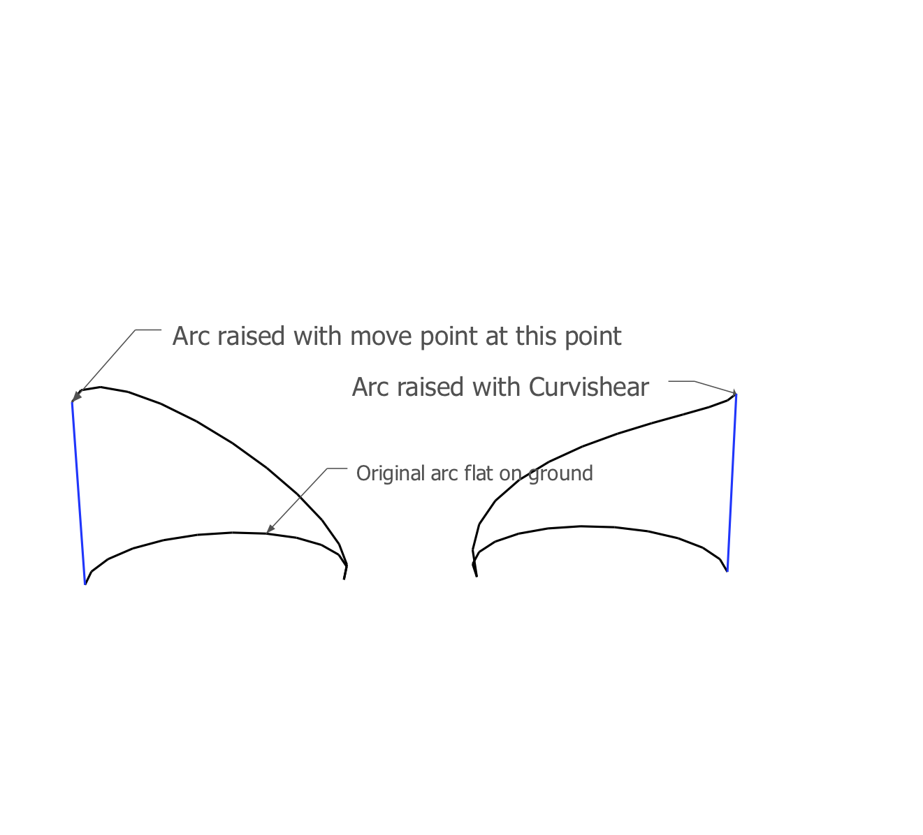
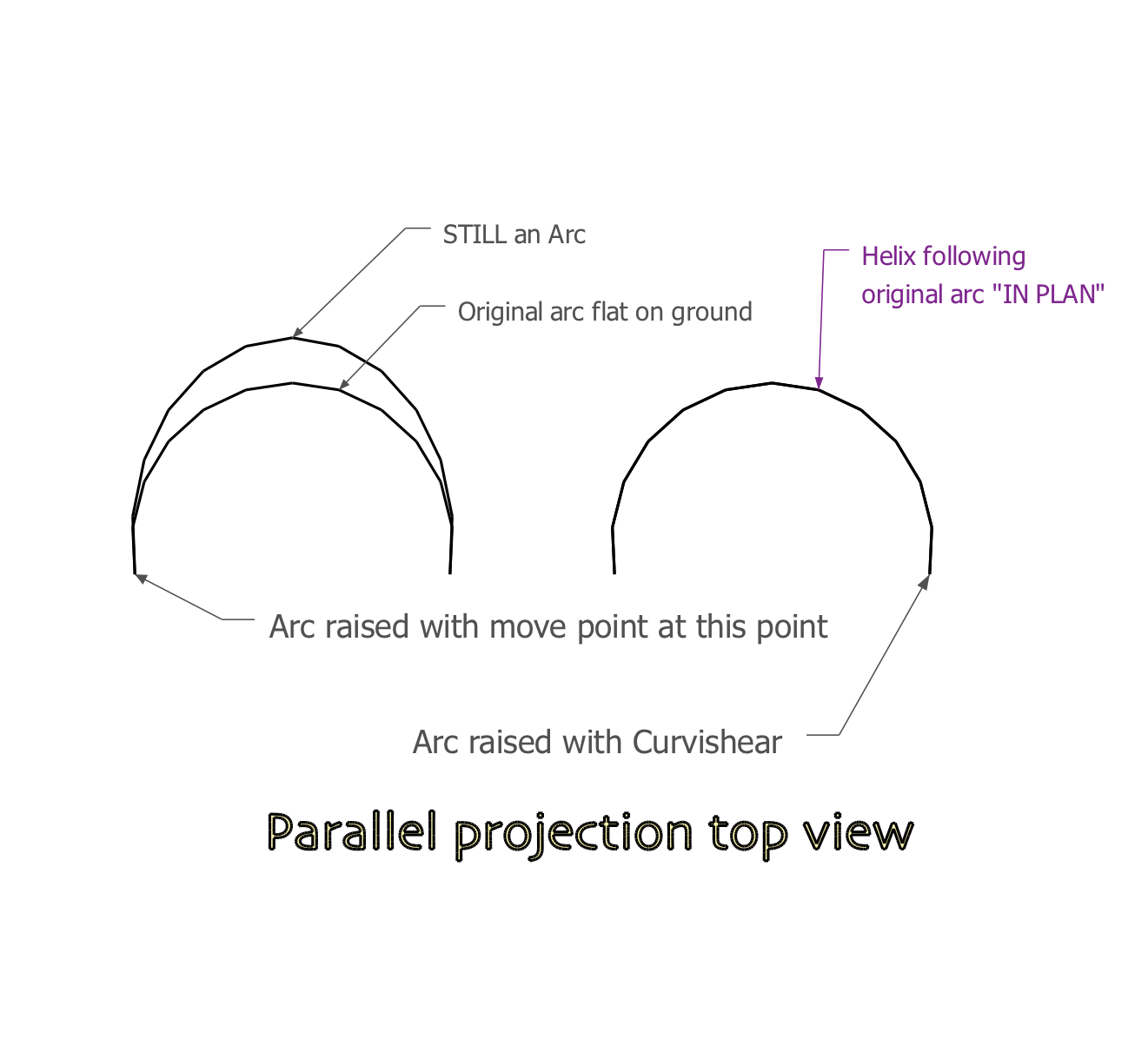
Moved end point (left side) is STILL an ARC. Curviloft(right side) creates a helix, obviously no longer an arc but it does not deform "IN PLAN" which is the OP complaint about the moved point curve.
@brookefox said:
Row 1 col 2 doesn't really follow original in plan, does it, because right the end has been moved (or was that a false horizon?)?
Ignore the horizon. In Plan here means viewed from above. The top row arcs are set back a little so they may not look the same size, but they are. It was easier to organize that way, sorry

Maybe these pictures (with more words) help. The lower arcs are identical lying on the ground. right above them are the arcs transformed to curves, with the vector blue reference line (same height). The second picture is an orthogonal top view with all four curves still in place.
-
Thanks, again, kind one.
How about (similar to Trevor's suggestion):
- arc
- face it arbitarily
- push pull
- tools on surface: connect two original end points
-
@brookefox said:
Thanks, again, kind one.
How about (similar to Trevor's suggestion):
- arc
- face it arbitarily
- push pull
- tools on surface: connect two original end points
[attachment=0:1d92todr]<!-- ia0 -->scaled arc-1.JPG<!-- ia0 -->[/attachment:1d92todr]
that makes a different shape than what's intended.
for instance, you can't make a spiral staircase (or screw thread) using the shape.. it would be wobbly(?) instead of smooth/continuous. -
Did you catch me cheating?
@unknownuser said:
that makes a different shape than what's intended.
I thought he wanted the plan views before and after to be the same and I thought they are with the method indicated.
@unknownuser said:
Try draw an half circle on one of the axes.... The projection of this new 'climbing path' on the 'ground' STILL should be a half circle - but it ain't - why ?
-
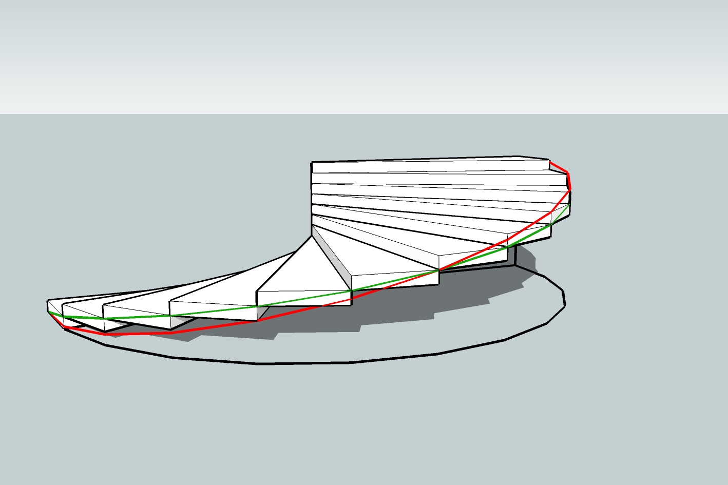
right.. the goal is the green line.. the red line is what happens when a plane intersects a cylinder (ala ArCAD-UK)
edit-
ie.. the green line's slope remains constant (it's a helix).. it goes over 3' / up 6" (which is what those stairs are supposed to be showing )… the red line's slope varies..
from the top, they look identical
-
I see what you are saying, and thanks for showing it, but I didn't think his goal was a helix; I thought he wanted the red line.
I wonder what his purpose wis (was/is).
-
the helix gives the same result you'd expect to see if you did this on a flat surface.. move one end of a rectangle's edge up and it will make a straight line.. as does the helix.
the intersecting a cylinder with a plane will result in some sort of sine curve(?) when flattened out..
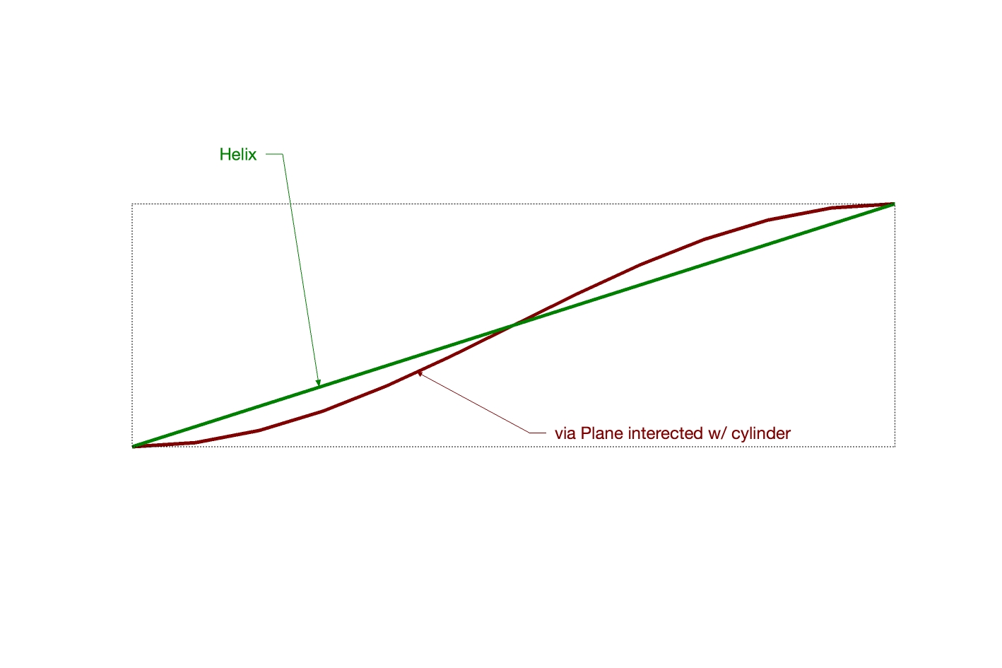
so going off that, i'd assume the helix is the desired outcome ??
(and he's probably trying to make a screw thread as mentioned elsewhere in the thread?)
-
Would someone point me to the original thread, please.
What view is that, Jeff? Seems like a side view of a cylinder cut by a plane is a straight edge, as you show for the helix....oh, you're showing the flattened out view, wherein they are reversed in their flatness, as it were. I guess.
If you could illustrate the flattening out that would cinch it all for a few moments, I feel sure. That's OK; I should accept that as a personal task rather than asking you to model it for me. I'm imagining this is getting stale. Thanks for hanging in.
-
this is the original thread.. the screw was mentioned (indirectly) in the 6th post.
the helix is the simplest (and probably most useful) form out of the two which is why I'm showing it (lots of info left out of the thread so I'm making some assumptions here)
the helix is a straight line that's being wrapped around a cylinder whereas intersecting a plane with a cylinder creates a more complex/compound shape.. it's an S-curve that's then being wrapped around a cylinder.. that's what the two previous drawings by me are supposed to be showing.
I can't make another drawing right now as I'm on a phone. -
Ever heard of Kito Raupp? A master of SU tricks.
[flash=640,360:bdb4kg75]http://www.youtube.com/v/IT5r3AQZBnw[/flash:bdb4kg75]
http://www.youtube.com/watch?v=IT5r3AQZBnw -
@gilles said:
Ever heard of Kito Raupp? A master of SU tricks.
i don't think kito ever heard 'righty-tighty lefty-loosey'

-
He may have read this

http://en.wikipedia.org/wiki/Screw_thread@unknownuser said:
By common convention, right-handedness is the default handedness for screw threads. Therefore, most threaded parts and fasteners have right-handed threads. Left-handed thread applications include:
Where the rotation of a shaft would cause a conventional right-handed nut to loosen rather than to tighten due to fretting induced precession. Examples include:
The left hand pedal on a bicycle.[3]
The left-hand grinding wheel on a bench grinder.
The lug nuts on the left side of some automobiles.
The securing nut on some circular saw blades - the large torque at startup should tend to tighten the nut.
In combination with right-handed threads in turnbuckles and clamping studs.[4]
In some gas supply connections to prevent dangerous misconnections, for example in gas welding the flammable gas supply uses left-handed threads.
In a situation where neither threaded pipe end can be rotated to tighten/loosen the joint, e.g. in traditional heating pipes running through multiple rooms in a building. In such a case, the coupling will have one right-handed and one left-handed thread
In some instances, for example early ballpoint pens, to provide a "secret" method of disassembly.
In mechanisms to give a more intuitive action as:
The leadscrew of the cross slide of a lathe to cause the cross slide to move away from the operator when the leadscrew is turned clockwise.
The depth of cut screw of a “Stanley” type metal plane (tool) for the blade to move in the direction of a regulating right hand finger.
Some Edison base lamps and fittings (such as formerly on the New York City Subway) have a left-hand thread to deter theft, since they cannot be used in other light fixtures.
The term chirality comes from the Greek word for "hand" and concerns handedness in many other contexts. -
Jeff, thanks for your contributions to this thread, useful stuff. As to which is the right solution to the OP I guess we will never know unless he comes back and posts. My initial reaction was he may have been trying to add a sloping cut to his semi-circle.

-
@arcad-uk said:
My initial reaction was he may have been trying to add a sloping cut to his semi-circle.

right.. that's what a helix is

lift one end of an arc and it will make a helix.. a continuous slope around the cylinder..intersecting a plane with a cylinder, while it may seem at first to create a sloping cut, actually creates something fairly complex and less usable.. it doesn't create a sloping cut -- it makes a cut that varies in slope (and won't continue upwards either.. it goes up for a semi-circle then back down)
dunno, i went through this stuff years ago and my first tries used similar methods as intersecting a plane with a cylinder.. it took a little while to figure out why the method wasn't working out properly but i eventually realized a helix is the proper shape..
i guess i'm being lazy in not fully explaining it and i know me saying "hey, just trust me on this" doesn't hold much weight but…. -
An helix is nothing else than a straight line wrap around a cylinder with angle.. I guess.
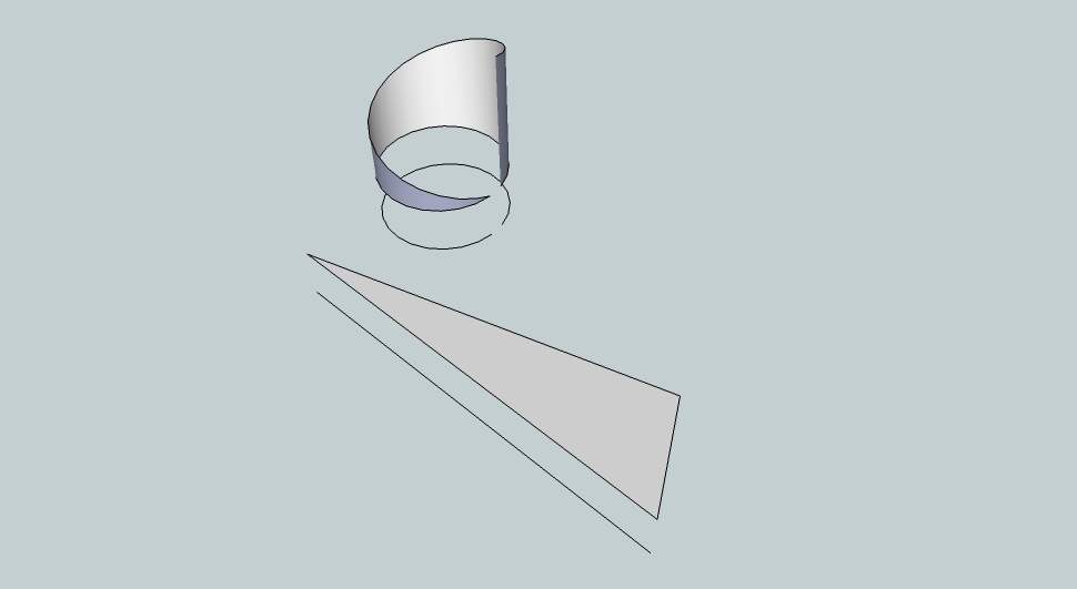
-
@arcad-uk said:
Jeff, thanks for your contributions to this thread, useful stuff. As to which is the right solution to the OP I guess we will never know unless he comes back and posts. My initial reaction was he may have been trying to add a sloping cut to his semi-circle.

As I did write earlier I just saw a video where the method was used to make a thread on a screw - and I could see that was wrong when you take it to the extreem - but I WOULD TOO HAVE exspected it to be THE method - why scale it up just because I move the end point along the normal vector to the original "arc" - to me the original arc IS a strait line wrapped around a cylinder between the two end points - why should it NOT continue to be that because I move the one end point ?
Why did the developers choose to scale it UP from the surface of the cylinder ?
Maybe it's tuff to do the coding for "what I would exspect" - then why not be more "naturel" and just tighten "the NON-elastic robe" between the two end points - to me it's NON SENCE to make the robe SUPER MAGIC ELASTIC so it lifts itself from the surface !
-
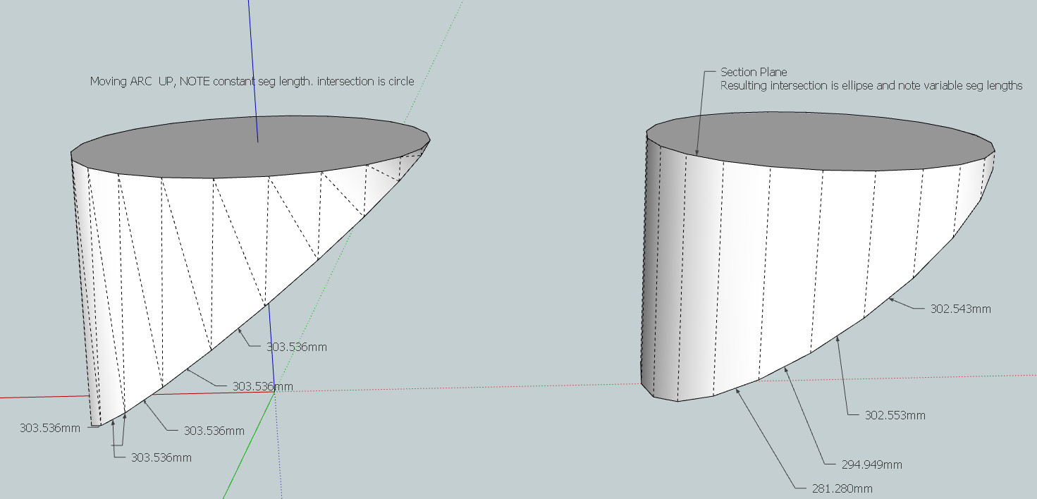 FYI
FYI -
@ksor said:
@arcad-uk said:
Jeff, thanks for your contributions to this thread, useful stuff. As to which is the right solution to the OP I guess we will never know unless he comes back and posts. My initial reaction was he may have been trying to add a sloping cut to his semi-circle.

As I did write earlier I just saw a video where the method was used to make a thread on a screw - and I could see that was wrong when you take it to the extreem - but I WOULD TOO HAVE exspected it to be THE method - why scale it up just because I move the end point along the normal vector to the original "arc" - to me the original arc IS a strait line wrapped around a cylinder between the two end points - why should it NOT continue to be that because I move the one end point ?
Why did the developers choose to scale it UP from the surface of the cylinder ?
Maybe it's tuff to do the coding for "what I would exspect" - then why not be more "naturel" and just tighten "the NON-elastic robe" between the two end points - to me it's NON SENCE to make the robe SUPER MAGIC ELASTIC so it lifts itself from the surface !
I'm with you ksor. like I said earlier, I too wish sketchup would act as you're expecting it to.. I believe it would be difficult to code and the UI would become more cluttered because there would have to be a way to differentiate between the current behavior and your expected behavior (in many situations, the current behavior is desired such as moving an arc between two points while maintaining an arc shape)
so sketchup would have to become more intelligent in its handling of curves etc but from what I gather via other similar requests, the developers aren't interested in making this happen..in short, you'll just have to use another method to properly draw this thing
Advertisement


