Drawings for milling ????
-
When using a mill for metal you aften need do something like the attach file.
How can I make such drawings ?
I did the drawing by using the LINE-tool to draw the "connected faces" - but there must be a better method !
-
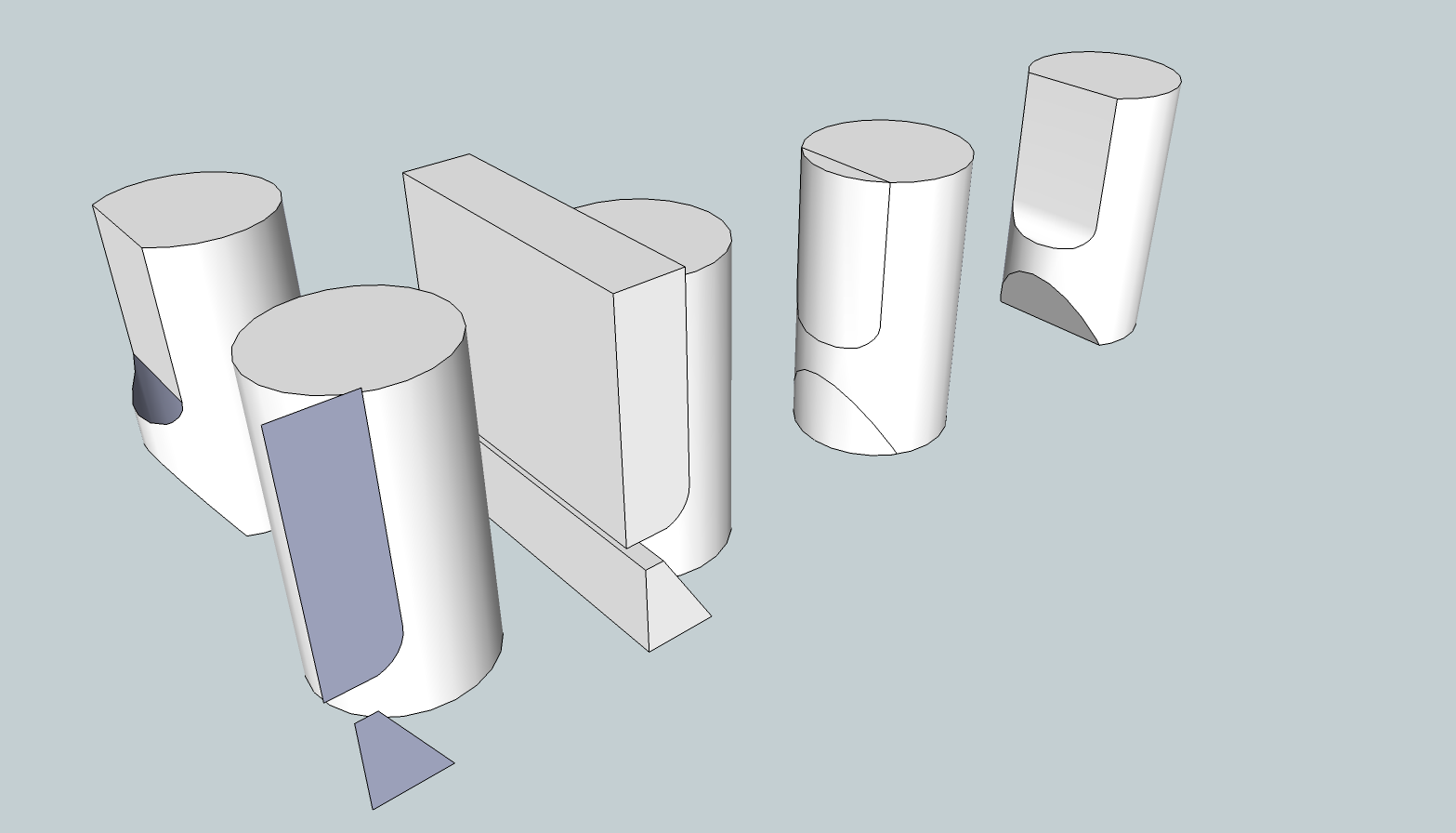
You could use a shape representing the volume of space through which the cutter would pass. Intersect it with the shape then delete the cutter and the waste.
-
@dave r said:
You could use a shape representing the volume of space through which the cutter would pass. Intersect it with the shape then delete the cutter and the waste.
Yeah, but try do it and show me by attaching file
-
I edited my previous post. No try. Just do.
And yeahbuts live in the woods.

-
Position/rotate, then intersect two or more suitable forms, and finally erase unwanted parts to leave the required 3d solid. Reverse/orient the object's faces so all of them look outwards consistently...
Use a group/component for these to avoid raw geometry clashes/sticking whilst positioning/rotating etc.
[Edit: Dave has now added an example to his earlier post...]If you have v8-Pro there are native 'Solid' tools to simplify the adding/subtracting/trimming etc of forms.
There are also a couple of 'Boolean' scripts to do similar work for 'Free' - one is free [by Oscar?] the other is inexpensive [available via Smustard.com?]...
Hello! It looks like you're interested in this conversation, but you don't have an account yet.
Getting fed up of having to scroll through the same posts each visit? When you register for an account, you'll always come back to exactly where you were before, and choose to be notified of new replies (either via email, or push notification). You'll also be able to save bookmarks and upvote posts to show your appreciation to other community members.
With your input, this post could be even better 💗
Register Login


Advertisement