How would you model this one?
-
Grow
Matrix
etc -
@tig said:
Grow
Matrix
etcThank you so much, TIG! But Matrix can array, scale, rotate randomly, grow does not work for these images showing below. Could you give me more information about how to model it? Thanks again!
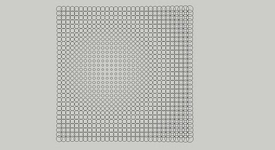
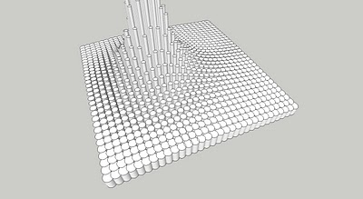
-
-
Or the sand box for move the cylinder?
-
@unknownuser said:
really? how?
Damned: Protrude works but gives a randomly result

Don't remember that it have not a progressive function
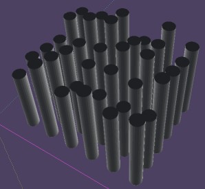
-
Using Grow on a component... process it 16 times to 'east', incrementing it to 'north' in each step; using the min to max values across half width, incrementing the Z values for each set.
Then copy/mirror all to 'east', then for all of the results you copy/mirror them to 'north', forming the 'mound'... -
Yes grow can make it but not in one time

I have used the "Exponential ZScaling" By lines / by quarter aera

And also Extrude edges by vector to Object by Tig

You must draw the curvated plan of the ceiling of the cylinders top by the Smoove tool of the Sand box or other tool!
+If you don't want to have your cylinders truncated
maybe you must first project a circle at each point of the vertex of the curvated ceiling made by the Smoove tool
the plug Component Spray by Didier Bur makes that
then use the Extrude edges by vector by from top to ground
-
Another method
As the Plug "Drop" can't intersect with vertices must make this little trick and so don't use "Drop":)
Object of the Extrude Edges is a simple plan as ground
Component circle must have axis at the middle of the circle!
For replace component : Select all components Lines
Menu Component / right click on the Component Circle / Replace Selected

Edit : in fact you can directly make the Spray with the Component Circle on the mountain!

So more speedy!
-
@unknownuser said:
Another method
As the Plug "Drop" can't intersect with vertices must make this little trick and so don't use "Drop":)
Object of the Extrude Edges is a simple plan as ground
Component circle must have axis at the middle of the circle!
For replace component : Select all components Lines
Menu Component / right click on the Component Circle / Replace Selected
[attachment=0:2lbzwogw]<!-- ia0 -->spray.jpg<!-- ia0 -->[/attachment:2lbzwogw]
Edit : in fact you can directly make the Spray with the Component Circle on the mountain!

So more speedy!
Thank you so much, Pilou!
-
@tig said:
Using Grow on a component... process it 16 times to 'east', incrementing it to 'north' in each step; using the min to max values across half width, incrementing the Z values for each set.
Then copy/mirror all to 'east', then for all of the results you copy/mirror them to 'north', forming the 'mound'...Thanks, TIG! I did some of them, but I could not make No.2
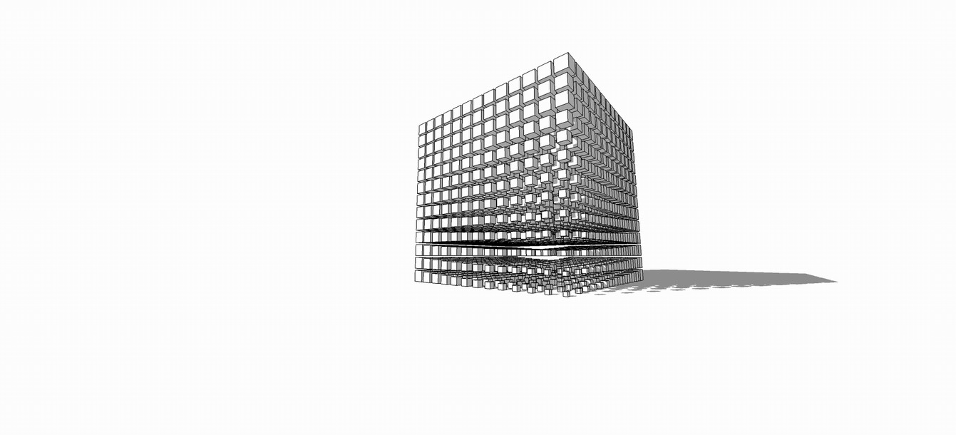
-
@unknownuser said:
Another method
As the Plug "Drop" can't intersect with vertices must make this little trick and so don't use "Drop":)
Object of the Extrude Edges is a simple plan as ground
Component circle must have axis at the middle of the circle!
For replace component : Select all components Lines
Menu Component / right click on the Component Circle / Replace Selected
[attachment=1:ij9juqvg]<!-- ia1 -->spray.jpg<!-- ia1 -->[/attachment:ij9juqvg]
Edit : in fact you can directly make the Spray with the Component Circle on the mountain!

So more speedy!
Thanks, Pilou!
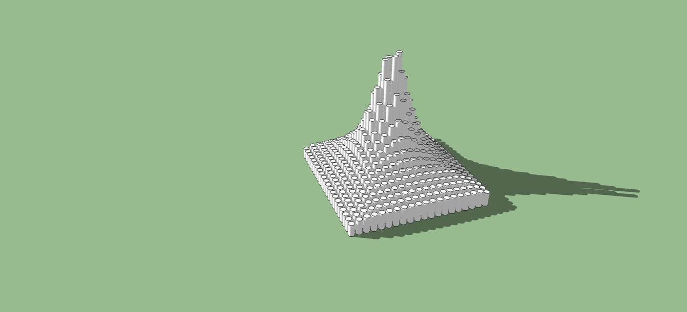
-
These pictures were taken from this thread http://forums.sketchucation.com/viewtopic.php?f=289&t=30749 about parametric modeling in SU.
If you have a look at other 3d programs, or. eg. grasshopper for rhino, you'll find that these results were archieved with the use of an "attractor" in conjuction with "chained" elements.
I cannot explain this in detail (i didn't how anyway
 ) but if you're interested just give it a look.
I find it very interesting as well as it gives you designing opportunities which are very hard to achieve by hand.
Good luck!
-
I have seen something similar at tgi3d. Not sure if these figures specifically can be done.
Advertisement


