Window components cut opening
-
Walt,
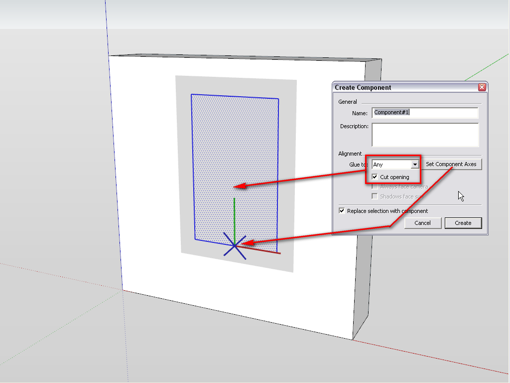
The file you posted just has loose geometry. No components. I created a gluing component from it and set it to cut the opening. Select the window component and look at how the axes are arranged. The red/green plane is the gluing plane. When you create the component you need to adjust the axes so the red/green plane is in the right plane and the right location. I just set it so it's on the centerline of window although that might not be where you wanted it.
-
Here is a little reminder I have made some days ago, attached to a useful nice Plugin thread ..
[Plugin]Hole on Solid tool v1.6 upadate Dec 14, 2011
The trick (don't know if others do the same): Make the opening profile the main component, given to it the gluing abilities. Then paste into it as a group or component the proper window geometry...
 simon
simon -
Thanks Dave I attached the wrong .skp to begin with that's why it was all primitives but your explanation about the axes was the missing link for me. Thanks again
-
Walt, I'm glad it helped. And for what it is worth, when you set the axes for the component, make sure the origin is in a location that makes it easy to insert them into the model. Your window might be easier to insert based on its left-to-right center line instead of the lower left corner the way I set it up. This is along the same lines as my tutorial on inserting knobs which I expect you've read.
-
@ simon le bon, thanks for that I have a lot of windows this can be very useful.
-
@ Dave I remembered that as I was reading your reply.
Thanks
-
hi everyone,
Dave, i've read your articles in FineWoodworking.
but i didn't get the idea of making component's gluing and cut opening.
i've posted the same question in a different post though.
i'll check the skp you've attached here and see if i can learn something.thank you Dave and everyone else here.
[edit]
Dave, how to check the component create checked items? i see that the component's blue axes is heading towards the model green axes there. could you help me to understand this better.
thank you for your time, Dave. -
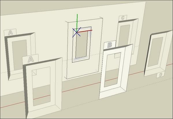
A gluing/cutting component has a special axis arrangement - the blue axis is always perpendicular to the face it's placed onto.
When you make a gluing / cutting component create it on a face so that its axes are automatically set correctly on creation... OR make it flat on the ground as [0,0,0] with it facing upwards, as if the face it will glue onto is the ground plane...
You can always change a component's axes after creation using the right-click context-menu 'change-axes' - picking the new axes in the required directions with red/green on the face and blue perpendicular to it... -
@tig said:
A gluing/cutting component has a special axis arrangement - the blue axis is always perpendicular to the face it's placed onto.
When you make a gluing / cutting component create it on a face so that its axes are automatically set correctly on creation... OR make it flat on the ground as [0,0,0] with it facing upwards, as if the face it will glue onto is the ground plane...
You can always change a component's axes after creation using the right-click context-menu 'change-axes' - picking the new axes in the required directions with red/green on the face and blue perpendicular to it...yes, i understand the axes setting a bit now, sir. thank you. got that from the skp Dave Richard gave above. i opened the window component and saw the red, green and blue axis.
i've made the correct axis setting probably in the last attempt i did. i posted in Component's Axes, Gluing and Cut Opening, -
Whenever it's possible, I start my gluing/cutting components on an existing face. Draw a rectangle, double click on its face (i.e. select both face & edges) and make component.
Notice that it is automatically set to glue and to cut opening in this case. Since it is still 2D, setting the gluing plane (grey area) is still easy. Set the component axes to some better place than the corner (with a window, the bottom midpoint is always better). If you miss this, you can always change the component axes later by right clicking. This component origin will also be the default insertion point when you drag it from the component browser later.

Also notice the special axis system of the component. Its gluing/cutting plane is always its red/green plane and the blue axis is "X'ed out". (When you right click on a component like this and save it "as" and open the new file, therefore the parts of the component are lying on its "back").So once you created the component as a starting ractangle, you can go on editing and add details to it and it will retain its gluing and cutting properties as long as there is a closed, co-planar loop of loose/raw edges on that gluing plane inside the component.
-
This looks so easy but I'm not sure what I'm doing wrong, when finish creating component and go back to edit component I don't get the crosshair blue axis like all of the above examples and it sure doesn't cut opening in surface. I created it like Dave, Tig and Gaieus. I think I have some blonde thing going here.
a little video http://www.youtube.com/watch?v=53A4RcfFMxE&context=C3a53393ADOEgsToPDskJzoHxREz1_PSvRmyKtAllx
-
Walt, you're right. Your video show how not to do it. I actually converted your window into a gluing and opening cutting component without having a "wall" to place it on but what you are doing in your video should work if your "wall" is not a component or group. Try it on an ungrouped surface ad see what you get.
-
Dear Walt and all,
I have always found the gluing and cutting option for a component, and the management of the axes remarkably unclear.
Here is the SketchUp Guide reference text.
Fortunately the SketchUp sages had come

Here is a reminder (avoiding doubling informations):
->@dave r said:
->The red/green plane is the gluing plane.
When you create the component you need to adjust the axes so the red/green plane is in the right plane and the right location.->when you set the axes for the component, make sure the origin is in a location that makes it easy to insert them into the model.
->
@tig said:
->A gluing/cutting component has a special axis arrangement - the blue axis is always perpendicular to the face it's placed onto.
->When you make a gluing / cutting component create it on a face so that its axes are automatically set correctly on creation
->You can always change a component's axes after creation using the right-click context-menu 'change-axes'
->
@gaieus said:
->Whenever it's possible, I start my gluing/cutting components on an existing face. Draw a rectangle, and make it a component. This component is automatically set to glue and to cut opening in this case.
-> Since it is still 2D, setting the gluing plane (grey area) is still easy.
->The component origin will also be the default insertion point when you drag it from the component browser later.
-> Also notice the special axis system of the component.
Its gluing/cutting plane is always its red/green plane and the blue axis is "X'ed out".->(When you right click on a component like this and save it "as" and open the new file, therefore the parts of the component are lying on its "back").
-> Once you created the component as a starting rectangle, you can go on editing and add details to it and it will retain its gluing and cutting properties as long as there is a closed, co-planar loop of loose/raw edges on that gluing plane inside the component.
Here is my cent:
->the gluing option (vertical, horizontal,..) refers to the faces of the model on which we are going to glue our component.
-> whatever the axes you choose, they are glued to the faces invariably the same. This represents a good basis to predict how to place the axes..

-> My solution(also described by Gaieus) constits in positioning the geometry (this is simpler if it is set as a group) around the existing axes.
See the video:
[flash=690,400:11xbb94w]http://www.youtube.com/v/xYPAg1S1kVw[/flash:11xbb94w]++simon
Advertisement


