Strange behaviour of SU when molding a door
-
Hi folks.
The Follow Me tool, when used to extrude a profile around a curved path may produce these problem if you extrude the profile inside the path. If you use it outside, the problem don't show.
However, with some combination of arc radiuses and segmentation for the path, it is possible to get good result, even if the profile is inside the path.
See all the scenes of the attached SU file for ideas.
-
@jean-franco said:
First, thank you to all for this interesting problem analysis.
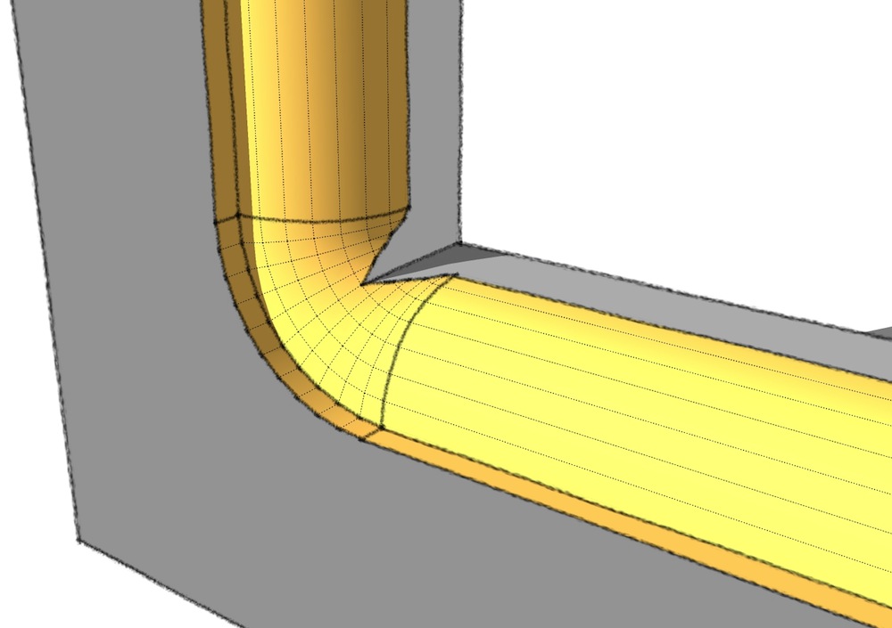
If you do that in your shop, in reality the corner will appear a little different as what Jeff describe.
Using the router after assembling the frame is effectively the way to go.
But you'll use a router bit with a bearing at the bottom, having a special radius.
How would you represent this in SU ?if you used one of those bits to cut the profile after assembly, it wouldn't turn out too sweet..
-
This discussion is getting more and more interesting

I found Jeff and Charlie's approaches very clever, even if I still haven't tried Charlie's at the top of the door, where the molding should also be curved.
I knew about TIG's Extrusion Tools but never found an application for me with the Lathe tool. So I spent some time in getting to grips with it. I think it is a very good tool but I'm experiencing some troubles with the angles of the curved top molding. After having extruded the two corners at about 79,371° (
 )I found the centre of rotation of the arc (Point a centre) and tried to extrude every section corresponding to each segment of the arc. The arc angle is about 21.258°, there are 12 segments for the arc, so every extrusion should measure 1.7715°. But I can only write 3 values after comma, this means adding some more imprecision to the angle. After three extrusions I notice that the segment of the extruded profile is not following the segment of the arc. The difference is very small but, after 12 extrusions the difference increases and this causes (at least to me) problems when intersecting geometries to clean up the molding.
Where am I wrong?
Jean (Lemire), thank you for your hints, but as far as I can see, your example ends up with rounded corners also internally, where they should be squared instead. Unless I didn't go deep enough in your example, I don't think it's the right solution.
Luca
-
We have to agree to disagree. Follow me has been around for some time and as with many things they get over taken by progress. To call it junk I think does a disservice to the creator. If the model is made carefully it works fine. As posted many times you must scale up by a relative large number for that to happen. More than the OP.
I have posted many times there is no tangent in SU by the mathematical definition ( unless you think a straight line is appropriate for consideration.). The designers have come up with an approach and if you don't like that why use it?
TIG's tools are very nice because they are adaptive in the sense a relative fixed geo is not required. -
@brandy20 said:
I knew about TIG's Extrusion Tools but never found an application for me with the Lathe tool. So I spent some time in getting to grips with it. I think it is a very good tool but I'm experiencing some troubles with the angles of the curved top molding. After having extruded the two corners at about 79,371° (
 )I found the centre of rotation of the arc (Point a centre) and tried to extrude every section corresponding to each segment of the arc. The arc angle is about 21.258°, there are 12 segments for the arc, so every extrusion should measure 1.7715°. But I can only write 3 values after comma, this means adding some more imprecision to the angle. After three extrusions I notice that the segment of the extruded profile is not following the segment of the arc. The difference is very small but, after 12 extrusions the difference increases and this causes (at least to me) problems when intersecting geometries to clean up the molding.
Where am I wrong?
instead of measuring and entering angles etc for those (unless you know the angle is 90.0º, or 25.0º etc.... try this:
-start the lathe tool
-choose rotation axis
-enter desired # of segments (12s <enter> for 12 segments etc..)
-enter 0 (zero) which will allow you to graphically choose the angle instead of entering the # in degrees..
(if the extrusion is rotating in the wrong direction at this stage, type <shift>C which will reverse the direction)

-
@jean lemire said:
.
However, with some combination of arc radiuses and segmentation for the path, it is possible to get good result, even if the profile is inside the path.
even then Jean, there are errors.. and if you're using sketchup as a drawing tool for real world construction, these errors are huge..
if you just want something to look neato on the screen then i guess you can get away with using but if you're trying to make accurate drawings, stay away from that tool unless it's being used for straight extrusions.. same goes for the offset tool (and actually, quite a few other circumstances/plugins have this problem)see attached skp.
-
@mac1 said:
We have to agree to disagree. Follow me has been around for some time and as with many things they get over taken by progress. To call it junk I think does a disservice to the creator.
it's nothing against the creator.. all i'm saying is that it is not accurate and anyone that needs accuracy in their drawing should steer clear of the tool..
@unknownuser said:
If the model is made carefully it works fine.
see, that's not true.. look at the examples i've posted and tell me where i went wrong or wasn't careful in the setup..
better yet, how about posting a carefully made model which shows accurate results with the follow-me tool on a curved path..
@unknownuser said:
As posted many times you must scale up by a relative large number for that to happen.
huh? that's nothing to do with it..
@unknownuser said:
I have posted many times there is no tangent in SU by the mathematical definition ( unless you think a straight line is appropriate for consideration.). The designers have come up with an approach and if you don't like that why use it?
i don't use it.. but when people are wondering why they're getting messed up results when using the follow me tool, i'll try to point out that the problem lies in the tool itself..
-
@unknownuser said:
@brandy20 said:
I knew about TIG's Extrusion Tools but never found an application for me with the Lathe tool. So I spent some time in getting to grips with it. I think it is a very good tool but I'm experiencing some troubles with the angles of the curved top molding. After having extruded the two corners at about 79,371° (
 )I found the centre of rotation of the arc (Point a centre) and tried to extrude every section corresponding to each segment of the arc. The arc angle is about 21.258°, there are 12 segments for the arc, so every extrusion should measure 1.7715°. But I can only write 3 values after comma, this means adding some more imprecision to the angle. After three extrusions I notice that the segment of the extruded profile is not following the segment of the arc. The difference is very small but, after 12 extrusions the difference increases and this causes (at least to me) problems when intersecting geometries to clean up the molding.
Where am I wrong?
instead of measuring and entering angles etc for those (unless you know the angle is 90.0º, or 25.0º etc.... try this:
-start the lathe tool
-choose rotation axis
-enter desired # of segments (12s <enter> for 12 segments etc..)
-enter 0 (zero) which will allow you to graphically choose the angle instead of entering the # in degrees..
(if the extrusion is rotating in the wrong direction at this stage, type <shift>C which will reverse the direction)

Jeff, that's great, thank you! It works very nicely,

-
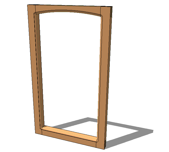
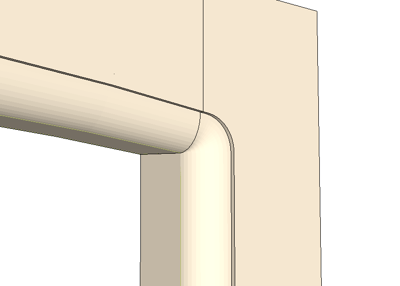
Molded door, using Extrude Edges by Lathe. Works very well and the workflow is pretty fast.
I'll also try Charlie's trick.
-
AND please remember that whatever method you use to make 'moldings', or any other swept-form for that matter, IF it will result in tiny facets it will fail. Sketchup and OpenGL don't like faces <~0.5mm or 0.01sq". Scale up. mold, scale down. Small facets can exists quite happily...it's just the accuracy issues in creating them in the first place that makes things fall over...

-
Hi Jeff, hi folks.
I agree with you about the use of SU for real world construction. After all, SU is a sketching program.
However, with carefull use, as is the case with all tools, it can be used to some extent.
See attached SU file for ideas.
-
@jean lemire said:
Hi Jeff, hi folks.
I agree with you about the use of SU for real world construction. After all, SU is a sketching program.
i dunno, sketchup is super accurate in most cases (especially when dealing with mid to large size construction drawings)..
i use the app with full confidence in my work.. it's just that over the years, i've learned (often the hard way ) where it breaks down and how to avoid the problems..
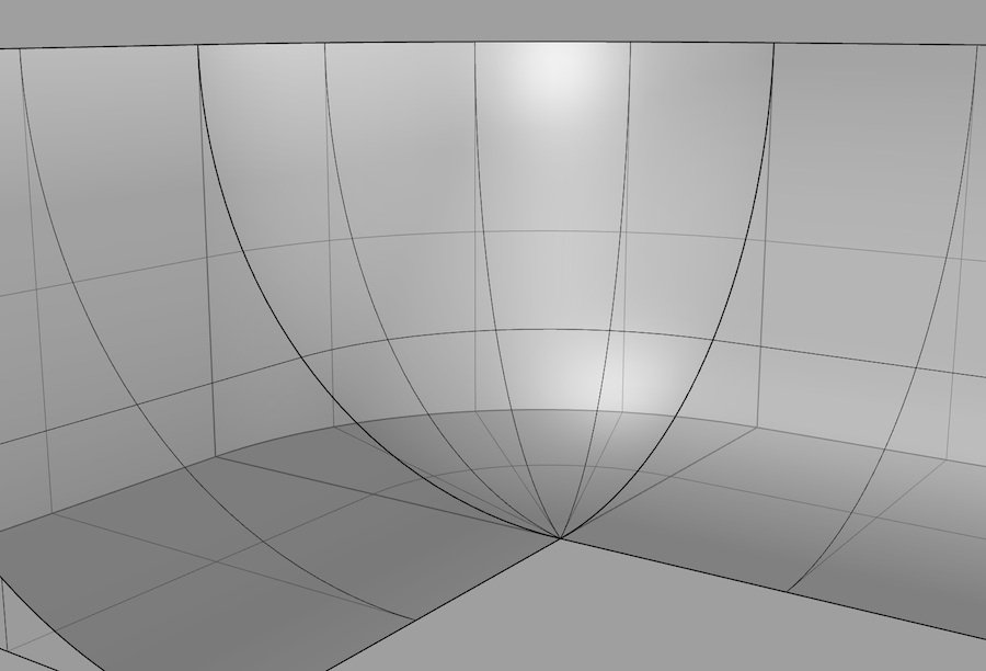
over the past couple of years, i've learned another app (nurbs based) which picks up the slack when sketchup fails.. using the two apps together instead of one OR the other is seemingly one of the smarter work related decisions i've made lately
but when it comes to situations like these, Rhino doesn't even bat an eye

-
@brandy20 said:
Molded door, using Extrude Edges by Lathe. Works very well and the workflow is pretty fast.
there are a couple of improvements/changes in the way EEbL works that would make my life a teenytiny bit easier but..
i feel like i've bugged TIG enough on the lathe tool already.. i'll give it another couple of months before i start with another round of suggestions
-
Per request http://sketchup.google.com/3dwarehouse/details?mid=97f6c7269341fe93483a6eca16661274 below the OP scale the model starts to have SU size issues.
Barndy20 please reconsider trying to mould the component approach it is dangerous -
@mac1 said:
Per request http://sketchup.google.com/3dwarehouse/details?mid=97f6c7269341fe93483a6eca16661274 below the OP scale the model starts to have SU size issues.
Barndy20 please reconsider trying to mould the component approach it is dangerous
lol.. i don't really know what to say.. maybe i'll just go with..you're absolutely right! follow-me is awesome!
-
if anyone other than m1 is actually interested in seeing the follow-me problem in another circumstance, have a look at the attached file..
this time, i use the offset tool as an example.. it shows the same exact error as with follow-me but with , it's easier to understand/explain where exactly the software breaks down
-
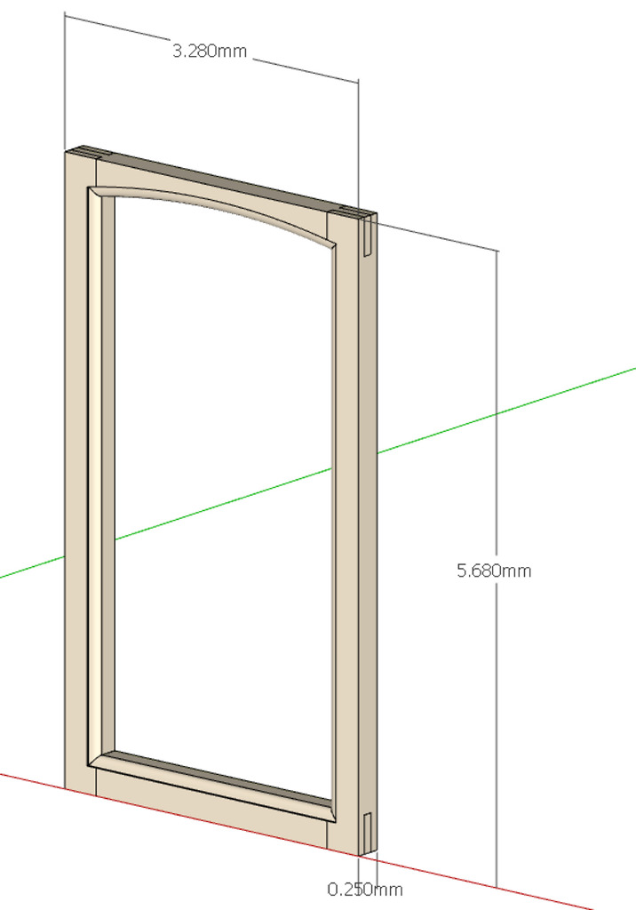 Not really I have better things to do.
For general interest here is the widow to scale using the follow me tool and better modelling practice.
Started extrusion further from bottom corner.
Use 2nd order Bezier to form better tangents than the arc tool. -
Mac1, isn't that all 100x too small ?? Look at the dimensions no door is 3mm wide ?
-
I'd like to steer back to the real issue with the Follow Me Tool that made me open this post. AND the problem arose when I wanted to use the follow me tool to have a molded curve on the outside and a 90° corner on the inner part.
If I wanted to mold a profile like in the attached file, that would not have been a problem with the Follow Me tool, and I think that the reason is pretty clear to all: Follow Me actually follows a path and cannot give you a curve on the outer edge and a 90° on the inner. We can try to get closer to a 90° scaling up the model and increasing the number of segments, but we we'll never have two orthogonal segments. That's it!
So, I think that, in my case, to have good results, we can try two different approaches: either use Charlie's one, that breaks up the path inserting a "quarter" (as he explained initially in this post) or go for Jeff's method, that uses the EEbl plugin.
I tried Jeff's method and works very well, so I'd be interested in seeing if there is another alternative to that, using native tools.
-
@brandy20 said:
I tried Jeff's method and works very well, so I'd be interested in seeing if there is another alternative to that, using native tools.
yeah, there is a way to do it with native tools and it's not too fun.. i used to do it like that before the Lathe and RoundCorner plugins were written..
i'm pretty sure i have a video of the process online somewhere.. i'll look around for it and post it if i find it..[well, another way to do it natively would be to draw a sphere then erase 7/8 of it (in the case of a 90º corner).. that's only going to work if your corner is a simple degree (meaning 30º, 45º, etc... not ~47.3948573º).. it's probably the fastest non-ruby way]
Advertisement


