Dimensions don't add up? Mystifying and frightening
-
I've been using SU for five months or so, but only a few hours a week, so I'm still a real a neophyte. With an increasing number of problems, the latest being that segments of a dimension add up to more than the Dimension tool shows for the whole length of an edge. If the segments were not colinear, that could be a correct result, but a lot of very close looking shows they are.
I'm using SU 8.0.4810 / OS X 10.6.8 on a MacBook Pro, Intel Core Duo
dimensions along the nearest edge of this building fragment don't add up
-
Hi David,
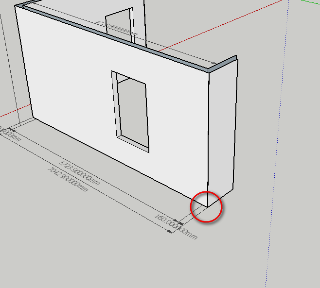
You have a small gap at the wall - too small to distinguish visually from any distance. Get the camera in real close to see it.
-
Frankly why are you dimensioning to anything more than 1mm ?
You are designing a building.
If it's build from muck, dust, mud, baked-clay, hewn-wood, slopped-concrete and warped-steel then you'll be lucky if it's within 10mm of your designed values anyway...
Years ago when you designed with hand-drawn drawings you would write '9" brick wall' - and everyone knew it wasn't actually going to be '9"' as bricks are not really that size - BUT they knew that it would be a one-brick thick wall approx 9" wide, and put it in the appropriate location.
Now with CAD, designers worry to the nth degree - but mainly for dimensional accuracy that can't be achieved in reality... Most building components are not made to those accuracies and few builders can't achieve 'perfection' - so start worrying about the detail and quality of your designs... and don't get hung up on fractions of a mm [or inch] when they don't matter one jot to what gets built...
-
Thanks, Jim! That seems to be at least part of the problem--though as far as I can see, the gap is way smaller than the difference in dimensions indicates. See my response to TIG, below, if you like.
@jim said:Hi David,
You have a small gap at the wall - too small to distinguish visually from any distance. Get the camera in real close to see it.[attachment=0:2txpcjov]<!-- ia0 -->0107.png<!-- ia0 -->[/attachment:2txpcjov]
-
Hi, TIG,
and first of all, thanks for your innumerable helpful posts and great plug-ins. They make SU a whole lot easider.
In this case, I'm using the super-precise dimensions in a (not too often successful) effort to make sure I'm getting my geometry the way I mean to. My tooltip inference flags keep disappearing--I have to reinstall SU about three times a month--and as a result, a lot of endpoints don't go just where I want them. I was hoping to be able to confirm by doing a really precise check of dimensions, which I realize won't be exact at all in real life. If I can ever finish the design.
David
@tig said:
Frankly why are you dimensioning to anything more than 1mm ?
You are designing a building.
If it's build from muck, dust, mud, baked-clay, hewn-wood, slopped-concrete and warped-steel then you'll be lucky if it's within 10mm of your designed values anyway...
Years ago when you designed with hand-drawn drawings you would write '9" brick wall' - and everyone knew it wasn't actually going to be '9"' as bricks are not really that size - BUT they knew that it would be a one-brick thick wall approx 9" wide, and put it in the appropriate location.
Now with CAD, designers worry to the nth degree - but mainly for dimensional accuracy that can't be achieved in reality... Most building components are not made to those accuracies and few builders can't achieve 'perfection' - so start worrying about the detail and quality of your designs... and don't get hung up on fractions of a mm [or inch] when they don't matter one jot to what gets built... -
HI,
I'm on also on a mac, so I thought I'd check your drawing to see if you where doing anything odd;)
First thing I spotted was you had profiles set to 2, which can give minor discrepancies at 0.000....etc, as SU can snap to either side of your 'thick line'.
I reset it to 1 and thought I'd do a simple image to show another 'snapping gotcha' with slightly out of parallel lines.
I added in a grouped rectangle, did an 'intersect with selected' so I could hide the model and have a flat plane to take all the dims off.
However, to my surprise, and bewilderment, if you drag the the NON PARALLEL Dim over the bounding wall for display, SU corrects it to the internal corner dim.
This is something I've never noticed before, has anyone else, mac or otherwise...

BTW... without trying to demonstrate the 'snap gotcha' your drawing dimensioned perfectly with profiles set to one...
Check it out, or is it me...
john -
@driven said:
However, to my surprise, and bewilderment, if you drag the the NON PARALLEL Dim over the bounding wall for display, SU corrects it to the internal corner dim.
This is something I've never noticed before, has anyone else, mac or otherwise...
to better see what's happening, draw a simple right triangle with more pronounced angles than u.monk's drawing.. (30º/60º/90º angles or so)
use the dimension tool on the hypotenuse.. the given dimension will depend on which axis you're locking to or whether or not the perpendicular snap is active.
-
@unclemonkey said:
......though as far as I can see, the gap is way smaller than the difference in dimensions indicates.....
The gap that Jim noticed is (only) 1mm, exactly the difference between the overall length and the sum of the 2*160+inner wall length. It's not way smaller.
@driven said:
First thing I spotted was you had profiles set to 2, which can give minor discrepancies at 0.000....etc, as SU can snap to either side of your 'thick line'.
I had to check this out so I set profiles to 20. It made no difference at all to accurately reproduce UncleMonkey's wall, incuding the gap and all its dimensions.
I don't think profile thickness has to do with accurate modeling.
Maybe UncleMonkey had length snap ON and set to something like 1mm?Jeff is right. If an edge is in a drawing plane (in plane with two axes or parallel to that plane) you'll be able to get 3 different dimensions in that plane. One of them being the 'Perpendicular' one reading the edge length. The other two in the drawing plane are along both axes of that plane.
Hello! It looks like you're interested in this conversation, but you don't have an account yet.
Getting fed up of having to scroll through the same posts each visit? When you register for an account, you'll always come back to exactly where you were before, and choose to be notified of new replies (either via email, or push notification). You'll also be able to save bookmarks and upvote posts to show your appreciation to other community members.
With your input, this post could be even better 💗
Register Login


Advertisement