Problems with modeling from Acad drawings
-
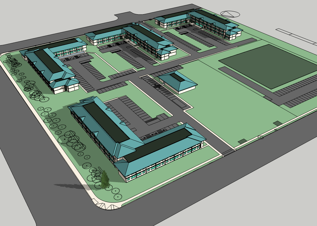
Although I have been working with Cad since the days of Dos, this is the first time that I am attempting to build a model from Acad drawings. Attached is the first schematic design model, of a low cost housing project that I am currently working on.
In the past, I could not understand the the problems people had with adapting Acad files to SketchUp. Broken, non planer, etc. Incorrect joints between lines, multiple lines in one line, untrimed lines, etc. were almost nonexistent with my own Cad drawings. With my client's Acad drawing however, I spent a day and a half, adjusting a 2d site plan so that the lines and surfaces were usable (barely) in SketchUp.
Is the problem universal, or is is occasionally? Why do my client's Acad drawing have so many problems? Is it a problem with the Acad application interface, or the Cad operator manner of input? Is there anything I can suggest to him so that his drawings don't require as much cleanup?
-
I don't work with a lot of CAD drawings imported into SketchUp but nearly every one I have used has had problems. Lines don't meet or they overlap. I've always put it down to making lines meet correctly not being all that important in ACAD or other CAD apps. Since we're always trying to create faces in SketchUp, there's no real tolerance for what looks like the sloppiness we see in those CAD files. I don't think I'd blame the people who make the drawings, though. I think it's the nature of the beast.
-
In general, I try to never use the actual lines from the CAD file as lines for my sketchup model. It's almost always a matter of putting it on a locked layer and tracing over it. That way I know that what I'm doing is clean and organized as I need it.
-
This is just my thoughts/ my opinion: I work with Autocad every day. Precise- not just accurate- input is crucial when you share these files with your consultants. Tiny imprecision does not matter visually, but continual drawing "by eye" with a system capable of high precision will result in cumulative errors. In Autocad select a drawing, select Front View. This will turn the drawing on edge. You will see all of the "smart blocks" such as doors standing in the midst of supposedly "flat" graphics. If the drawing was prepared ignoring the opportunity to use available snaps, you will also see vectors skewed above and below the zero plane. Go back to top view and everything looks in order, but you need to move something or insert something at that intersection over there. So you drag it over to that intersection and you wait for the intersection snap inference to light up. Say you were drawing circuit diagrams for spaceships that you will be travelling in. Good luck.
The problem gets worse when you do the higher level dwg management available, such as xrefs and registration of multiple levels in a large site.
Poor spelling and grammar may not kill anyone, but poor planning certainly can. -
Typically, I will do the following when bringing in cad:
-
Isolate only the layers I need
-
Wblock that to a new file, open that file, change all to layer zero, flatten, purge, save as acad 2000
-
In sketch up I will bring it in as a group and lock it. Then trace over the lines. Sometimes I will use the actual cad, but it is a case by case evaluation. Hint: curves cause problems.
It isn't as smooth as you think it would be. Sometimes I like to work off a jpg of the concept instead of the cad.
If you are doing an illustration, if it looks right, it is right.
-
-
@honoluludesktop said:
In the past, I could not understand the the problems people had with adapting Acad files to SketchUp. Broken, non planer, etc. Incorrect joints between lines, multiple lines in one line, untrimed lines, etc. were almost nonexistent with my own Cad drawings. With my client's Acad drawing however, I spent a day and a half
I think this pretty much hits the nail on the head. The problem isn't with either program - unless you count the fact that humans use them. You can't expect everyone to produce the kind of quality you do.
-
Thanks for the classification and help, fellows.
My Cad application requires upon inserting a line, the operator identify where it's attached to another entity. For example, with almost no effort the command "insert line: " is clarify by "on", "end", etc. in order that the line is precisely placed. If no clarification is given, the line begins on z=0.0, and where ever the digitized is placed. But even then, it's easy enough to trim the lines perfectly.
One of the biggest problems is with attempting to place a surface on existing coplaner line ends, if there was a slightly overlapping line intersecting the face I was attempting to create, SketchUp refused to insert the face until I corrected the Acad drawing. Can anyone tell me if it matters that I import dxf or dwg files? Other problems I faced, was the weld.rb would frequently cause SketchUp to splat. Is that common?
I can't believe that I spent more then a day to face that site plan. This morning I was advised that the site plan has been changed.:-( Given the condition of the drawing, I will have to spend another day prepping the revised plan for SketchUp. Is there no specific advice I can give my client? Surely AutoCad has similar commands to my Cad application.
-
I get DWG's from many architects every day.
What I've seen is that many work with AutoCad in a very visual way - as long as it looks ok in the print then it works for them. But that leads to problems when you try to take the data out into another application - especially to be transformed to 3d.Some are good to use snaps and take care of cleaning up the drawing ensuring there are no overlapping lines etc - but most don't. Many doesn't even use blocks efficiently - very often I get drawings with hundreds of exploded blocks representing trees or stairs or whatever. Some time I even get drawings where there's a 3d siteplan which they've used as a underlay, but not checked that it was 3d or bothered to convert it to 2d - so I end up with very oddly shaped drawings.
It's a real pain - and I never ever trust a DWG. I always import into a temp SU model and clean up. I wrote Edge Tool's Open Gap inspecting function just for these problems.Summary: Reason why many DWGs are messy: people are sloppy and doesn't understand the tool (AutoCAD) they use good enough and they a haven't learned to use efficient workflow - not for themselves and certainly not for preparing the CAD data to be further used.
In my experience, most people don't seek out ways to improve their workflow - instead they make do what seems to visually work and get the work done in a pinch.</rant>
-
Well, there are many reasons AutoCAD doesn't play well with others - monopoly, closed and proprietary dwg file format, lack of information and above all the SketchUP's nature - mesh modeler! You can't expect the same level of precision in SketchUP - there is no real geometry - splines, curves, circles, arcs and etc. There are only lines, vertices and faces. I have a friend who is developing a furniture plugins for AutoCAD and He is always complaining about the lack of information Autodesk gives him about the internal structure of the solids. He ported the same code to the BricsCAD and it was a breeze - completely opened system for building external applications. Move on to a more advanced software or just draw everything in SketchUP from scratch - I did the first.
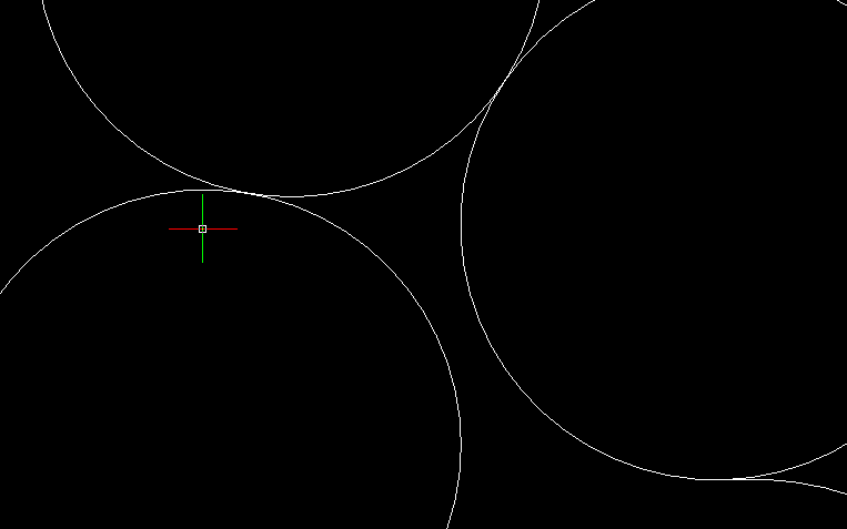
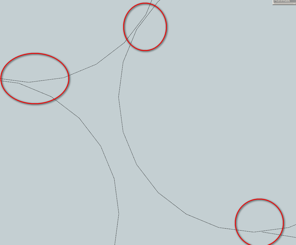
Little example - the circles and the arc are tangent. Imported in SketchUP - they even don't touch anymore.
-
OK, guess I just have to deal with my client's drawings.
-
I make shop drawings so your woes are the story of my days.
As was pointed out above, the biggest cause of inaccuracy is coming from the client's end but I often work with drawings that have been converted - from VectorWorks to PDF or PDF to DWG or whatever. This process introduces inaccuracies due to how the software is reading the file. I use a program called Print2CAD to convert PDFs to DWG but it's only accurate to something like .003". Not a problem for someone looking at the drawing but it makes the drawing unusable for me unless I re-draw.
I find SketchUp to be a useful tool in this situation. Sometimes I get drawings that have so much useless data in them (deleted blocks, etc.) that it's worthwhile to run them through SketchUp and back out again as DWGs. That results, as you know, in every line segment being a separate line which is a problem in itself but I've found ways to work around that.
-
I have this problem even within my own office!
 Unfortunately, like many of the other folks here, I believe it is primarily human sloppiness. However, there is also an element of sloppiness in Autocad... for example, if you have the perpendicular and/or intersection snap turned on, you can get a snap that you didn't want. Or if you're going for an endpoint, but that line is just a little too long, you can draw a non-orthogonal line. Offset that and keep going and you've not started a cascade of trouble!
A few Autocad commands I've found that help:
-
overkill - deletes duplicate lines. Doesn't get overlapping ones, but at least it's a start.
-
For curves, I use "Break at Point" (it show's up as _break, but that's the usual command... I've always used it from the "Modify" toolbar). If a curve is intersected by a line, I break it at the intersection. That way when I get it into SU, the curve will always share an endpoint with the intersecting line.
-
pedit with the "multiple" option, then join as many as I can. This is especially helpful for building footprints, contours, and curbs. By making as many continous (and closed) polylines in Autocad, it saves a lot of time in SU. I know there are plenty of plugins for adding trim, extend, and fillet functionality to SU, but I like to do most of that in Autocad.
I often isolate layers and save them out separately to import into SU so they come in as components. A little more time up front, but helps speed things up in the long run.
I don't think there is any solution, but it's great to hear everybody's process for dealing with this perenial problem.
-
-
We use Autocad / SketchUp all the time and are back and forth between the 2 programs constantly.
If we produce the CAD drawings - no problem 99 % of the time.Occasional problems occur when curves turn into straight lines - sometimes you get clashes where previously in the CAD data you didn't. If you're aware of this SketchUp limitation you can get around it most of the time.
.........
If another Company has produced the CAD drawings then sometimes we have problems.
In other words, the problem you are experiencing is most likely not an Autocad problem.If your CAD operators are using AutoCad as opposed to another CAD package and exporting as dwg / dxf out then the problems are most likely to be CAD operator error ie sloppy drawing.
Zoom in to some of the linework junctions / intersections in Autocad - are the joins good ???
........
Some CAD packages that export dwg / dxf (ie none Autocad) can mess the data up.
We've been on the receiving end of some of this junk also - can be a real nightmare.
........
Make sure your CAD operators are using the Snaps correctly in Autocad - End Point, Mid Point, Perpendicular etc.
All linework should be crisply snapped together - no over / under shoots.
Get them to turn off Nearest Snap - or use with caution - can be lethal in the wrong hands !!!
.........
Data Clean Up (in Autocad)-
Turn drawing edge on - you should see a long flat line / lines. Anything above or below (0) is floating or drilled into the ground and needs fixing. (Manual Fix or FLATTEN)
-
FLATTEN Command - makes everything 2d
-
OVERKILL Command - eliminates duplicates
-
PURGEALL Command - Cleans out unused Blocks / Layers etc
.........
Hope this Helps
Howard L'
-
-
In Autocad, if you click on a vector you should see blue "grips". Right click on one of the grips select properties in the fly out menu. A tab should appear at the edge of the screen with a scroll window. Find the Z start, Z end. Edit the data in each of these fields. That's for one at a time. There is also a way to look globally at properties for all items whether polylines or vectors or arcs or whatever and look at these properties to find z values which can be corrected. Smart Blocks would have to be dumbed down by exploding, sometimes twice, before squashing to zero but you will lose 3d data you may have relied upon.
The only running snap I keep on is Intersection. You can Shift+right click to bring up snap context menu where you can change momentarily to any available snap. One I like a lot is Mid between 2 Points. This can be used for the "from point" and the "to point" for copying, mirroring, moving, and rotating and so on.
-
@honoluludesktop said:
One of the biggest problems is with attempting to place a surface on existing coplaner line ends, if there was a slightly overlapping line intersecting the face I was attempting to create, SketchUp refused to insert the face until I corrected the Acad drawing. Can anyone tell me if it matters that I import dxf or dwg files?
can you post a screenshot here
@honoluludesktop said:
Other problems I faced, was the weld.rb would frequently cause SketchUp to splat. Is that common?
I've never had that problem. I'd suggest you one useful plugin Makefaces ..it's available for free on smustard. You should surely give it a try. It's really useful plugin. I work with cad files a lot on sketchup and find this plugin really handy.
-
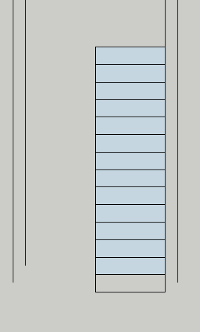
First is imported dwg
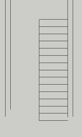 Then is attempt to surface steps. Note the lowest thread failed to surface.
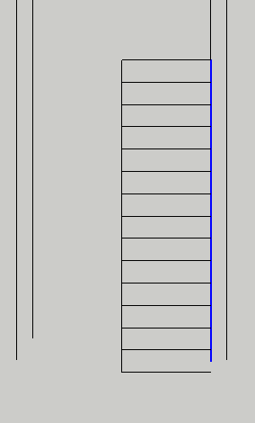
 Then, clean up of extra lines.
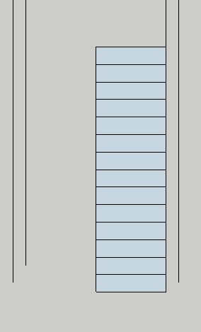
 Then, good surface.
 Detailed example of crossing line fragment.
 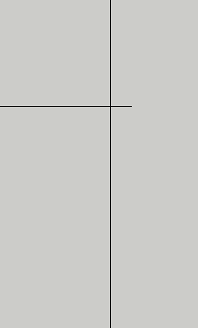 Because you asked, I looked more closely at the problem. The line fragment is very small, maybe the problem has to do with SketchUps defaults as to selecting inferencing points.
 -
@honoluludesktop said:
closely at the problem. The line fragment is very small, maybe the problem has to do with SketchUps defaults as to selecting inferencing points.
Try my Edge Tools 2 plugin, I got a tool there that highlights open ends and tries to close them, or remove tiny edge fragments.
-
I will vouch for thomthom's Edge Tools. Very effective. Salute to you, Thomas!
-
Thanks for the heads up, sounds like it will be a big help.
-
+1 on this one. This is the way I always do it.
@yahellid said:
In general, I try to never use the actual lines from the CAD file as lines for my sketchup model. It's almost always a matter of putting it on a locked layer and tracing over it. That way I know that what I'm doing is clean and organized as I need it.
Advertisement


