[Plugin] CADup
-
TIG (c) 2011 - 2013
All Rights Reserved.
THIS SOFTWARE IS PROVIDED "AS IS" AND WITHOUT ANY EXPRESS OR IMPLIED
WARRANTIES,INCLUDING,WITHOUT LIMITATION,THE IMPLIED WARRANTIES OF
MERCHANTABILITY AND FITNESS FOR A PARTICULAR PURPOSE.
Script: CADup.rb
Usage:
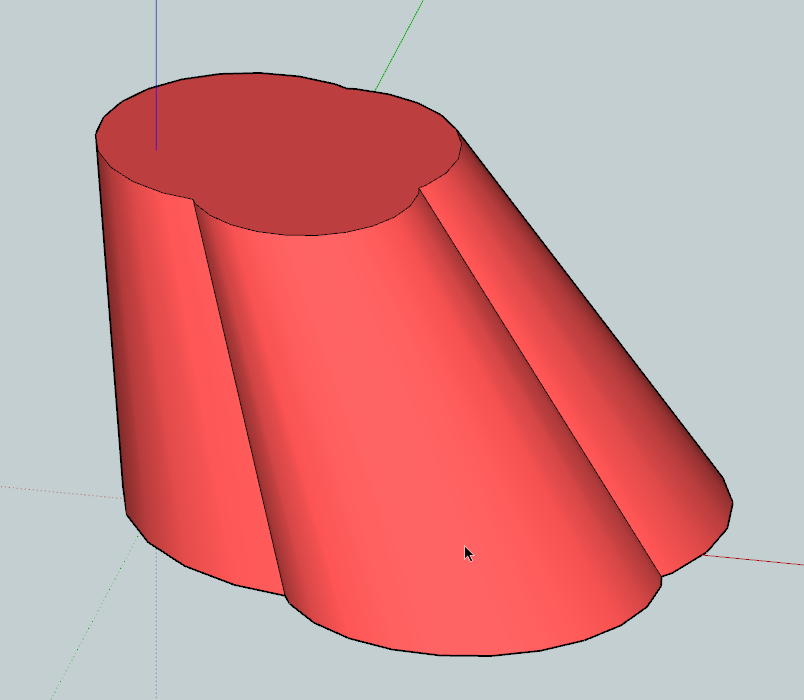
This makes lines drawings of views of a Group or Component-Instance ready
for use in a CAD program.
It is best to use this tool in an uncluttered SKP so that the intersections
of entities needed to do the complex geometry calculations are not
compromised by other unrelated entities [even if they might be 'hidden'].
Also place your Component-Instance OR Group with its insert-point at the
ORIGIN. If it is not located there then a copy of it is placed there,
however, ensure there is nothing else in the vicinity of the ORIGIN,
including any 'misplaced' Component/Group itself.
It's recommended that you select your component and right-click save_as to
process it as an external isolated component if possible.
Do NOT try and process a whole building with furnishings and fittings - the
amount of data in that collection of things will just 'kill' Sketchup!So, select your Component-Instance OR Group [and nothing else].
Pick 'CADup' off the 'Tools' menu [or type 'cadup' or 'skad' in the
Ruby Console]
If there is not one Component-Instance OR Group selected there is an error-
message.
'CompoName' is the Component-Instance-Definition's name, OR if a Group is
selected then the Group's name [or 'Group' if the Group is 'un-named'].
It runs with information displayed in the Status Bar and the view refreshed
after each step [v7+ only].
It creates a new Component called 'CompoName[SKAD]' on layer 'SKAD'.
If that name is already used it's incremented with a #1, #2... suffix...
Within that it makes a temporary grouped and exploded version of the
selected Component/Group located on the ORIGIN. At the end this temporary
group is erased and the selected Component/Group is replaced where it was.
It has a flat 3d-text label which reads '3D' on layer 'SKAD.TEXT'
[it's name is 'TEXT'].
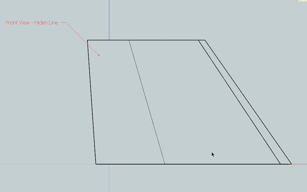
It then creates the 6 flat 2D orthogonal views of the Component/Group
within the 'CompoName[SKAD]', in turn: they are named:-
TOP
BOTTOM
FRONT
BACK
RIGHT
LEFT
[Equivalent to the Plan and Reflected-Plan, and the South, North, East and
West Elevations respectively]These are each grouped and named 'SKAD-TOP', 'SKAD-BOTTOM' etc [each is on
Layer0].
Within each view's group there are sub-groups:-
a) 'TEXT' on layer 'SKAD.TEXT' which is a flat 3d-text label which reads
'TOP', 'BOTTOM' etc.
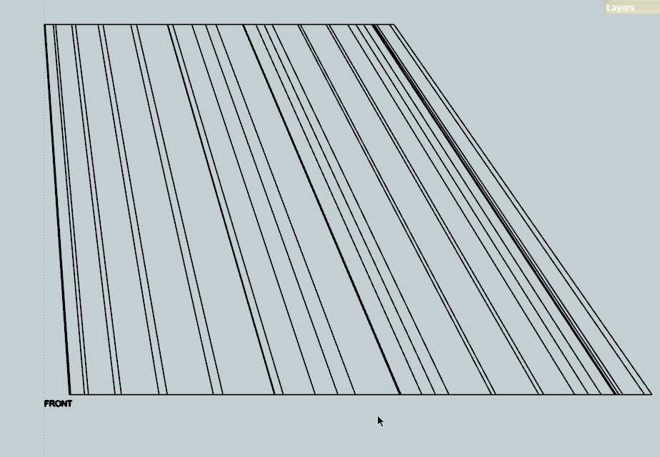
b) 'TOP-CONT', 'BOTTOM-CONT' etc [each on layer 'SKAD.CONT'] which contains
all of the CONTinuous solid edges that would be seen in each view.
c) 'TOP-HIDN', 'BOTTOM-HIDN' etc [each on layer 'SKAD.HIDN'] which contains
all of the HIDdeN edges that would be obscured in each view, also has any
hidden/soft/smooth edges in it - e.g. the curved surface of a cylinder.
d) 'TOP-CIRC', 'BOTTOM-CIRC' etc [each on layer 'SKAD.CIRC'] which contains
all of the CIRCles [and arcs] that are perpendicular to each view with a
small + at their centers - the + is on a layer called 'SKAD.CPTS'.
Note that the segments of the circles/arcs are also shown in the 'CONT'
version as individual lines - however, exporting a 3D DXF/DWG will export
the separate layer's entities as Circles/Arcs and these will be identified
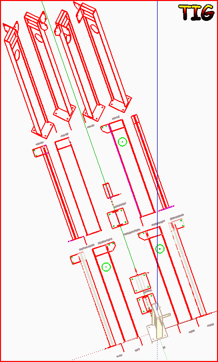
as those types of object in the CAD program - useful for 'drilling' etc.A collection of 6 SECTions is added - similar to the 'view' but with it
cutting the selected object at its center and having an additional grouped
set of lines 'SECT'. The are name after the direction of the section-view
not like the views them selves - so the view 'TOP' shows the top looking
down but the 'SECT-TOP' shows the underside of the top looking up.
The SECTions are named:-
SECT-BOTTOM
SECT-TOP
SECT-FRONT
SECT-BACK
SECT-RIGHT
SECT-LEFT
[Equivalent to the Internal-Plan and True-Ceiling-Plan, and the
Sections looking South, North, East and West respectively]These are grouped/layered etc in a similar way to the 'views'
A collection of the 4 flattened AXOnometric views is added.
They do not show hidden lines or separate circles, but are otherwise
similar to the 'views'.
Each is dimensionally correct in the Y and lines that are at 45 degrees to
the main axes. The AXOnometrics are named:-
AXO-NW
AXO-SW
AXO-SE
AXO-NEThese flat 2D view-groups are arranged on the z=0 plane.
They are arranged logically around the 3D version, oriented consistently.
They are spaced equally using the variable 'gap' which is set to 100mm at
the start of the code - it can be adjusted - note that it must be > 0...
The 3d-text labels' height is always gap/2 - i.e. default is 50mm.
The Circles' '+' cpt-marker is always gap/4 - i.e. default is 25mm.
The CADup default name="SKAD" is also set at the start of the code, and
this can be changed if desired...It's a good idea to have your current Style set to use 'Material by Layer'
and color the various layers to mimic CAD colors etc - see below...***Be patient - there are lots of operations to complete...
You can of course edit the separate view-group parts - e.g. erasing some
lines etc that you think are not needed.
Once the set is complete to your satisfaction you can export the new
collection to a separate SKP [right-click 'Save-AS...'] and thence as a
DWG or DXF to use in a CAD program.***The layering of the parts is specifically tailored to suit this CAD use.
If your CAD template file has the plotting pens set be 'by layer', then
you can set the layer 'SKAD.CONT' to be a medium/thin solid pen-style, the
layer 'SKAD.HIDN' to be a fine dash/dot/hidden pen-style. The 'SKAD-CIRC'
layer can also be used for hole-drilling etc or merged with an edited CONT
layer as desired. The 'SKAD-SECT' layer should be set to a thick solid
pen-style to display the section-cut appropriately.
Once you have a set of layers set up for this you can save a CAD DWG as a
template [DWT] and reuse that to make new DWGs of this type, inserting the
individual SKP>DWG files as Blocks and arranging and editing then as
desired...
Donations: By PayPal.com to info @ revitrev.org

Version:
1.0 20110215 First Beta Release.
1.1 20110218 A Group OR an Instance now processed.
Edges within any Groups/Instances within the Selected Object
are now reproduced on appropriate layers.
Edges that are hidden/smooth/soft in the Selected Object are
now reproduced on the HIDN layer.
Spacing of Views etc improved.
Has a trial version of SECT-BOTTOM only - for feed-back...
Has a trial version of AXO-SW only - for feed-back...
1.2 20110221 Container now made into a Component for easier export to SKP.
All SECTion and AXOnonmetric views added.
Arrangement of parts adjusted and the use of the original
selected object has be modified to minimize 'clashes'.
Default name 2CAD becomes SKAD.
1.2a 20130830 Now has ArcCurveTests.rb within its RBZ for backwards compatibility etc...
Please download the latest version from the SCF PluginStore http://sketchucation.com/resources/pluginstore?pln=CADup or from within SketchUp itself using the SketchUcation Plugin Store toolset...
-
Strange that was not yet existing!

-
-
Great idea for a plugin!
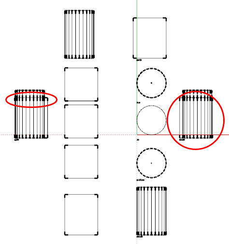
I tested it with a cube and a cylinder as one component but it add the lines of the object behind the object in front for the elevations. See image and the red circles. I also tested a more complex components with a lot of nested component and it did not like that...
Hope this helps what I think will be a very useful plugin, cheers!
-
@jsteacy said:
Great idea for a plugin!
I tested it with a cube and a cylinder as one component but it add the lines of the object behind the object in front for the elevations. See image and the red circles. I also tested a more complex components with a lot of nested component and it did not like that...
Hope this helps what I think will be a very useful plugin, cheers!It shows ALL lines but puts 'hidden' ones on a special layer...
Change you Style display to 'Color by Layer'.
Make the HIDN layer 'pale-gray' to mimic CAD's dash-lines and then the CONT layer 'red', and the CIRC/CPTS layer 'green/dark-green'...
You'll see the result better.
It's intended for CAD use later, so in the SKP it won't look so good unless you have this type of material-setting...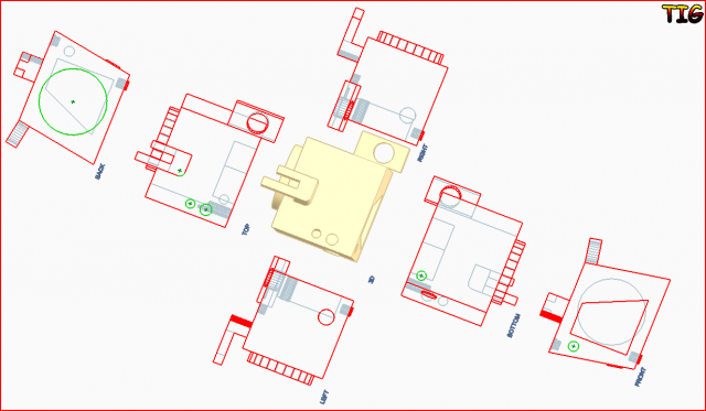
![2CADexample[NOTcolorByLayer].PNG](/uploads/imported_attachments/l39H_2CADexampleNOTcolorByLayer.PNG)
-
ahhh, helps if I read, thanks
-
Thank you. I just needed it

-
Thank You!
-
Good news:
I am going to extend CADup to include the 6 centralized sections.
I am looking at adjusting the way it handles 'surfaces' with hidden/smoothed lines, e.g. splitting the geometry onto new layers for these and the other outermost edges etc.
I shall be adding an example CAD template [dwg/dwt] with its layers set appropriately for heavy/medium/thin/dashed lines etc pstyles, plan view etc, that you can use to set up new sheets and import the CADup output as dwg/dxf blocks...
I'll be writing a tutorial.Bad news:
Won't have time to do it for a few days...
-
Good news! What about handling groups also?
-
@dedmin said:
Good news! What about handling groups also?
Yes I will also be adding support for using CADup on a selected group [as well as its current component-instance] AND for finding all edges within groups and component-instances that are nested within the selected object's entities...
-
-
Great looking plugin TIG!
Thanks very much for this, you're going to make a lot of people, especially product designers and engineers very happy!
Tom
-
@dedmin said:
:thumb:
This is in BricsCAD:
http://www.screencast.com/users/dedmin/folders/Jing/media/67e9351d-d895-487d-849d-5424b73e1cb5I see it makes iso/axo views... I was also thinking about how I might incorporate that in CADup...
-
@tig said:
@dedmin said:
:thumb:
This is in BricsCAD:
http://www.screencast.com/users/dedmin/folders/Jing/media/67e9351d-d895-487d-849d-5424b73e1cb5I see it makes iso/axo views... I was also thinking about how I might incorporate that in CADup...
Maybe based on the component/group axes or world axes - as two options. Because You can't be sure what are the front/back/right and etc. for a given component.
-
This is a very nice addition.
I have tried a couple of files, the first quite simple worked well.
The second caused the program to get into a loop where I had to force quit SU. I am on a Mac.
The file I had trouble with is proprietary so I cannot post it but would be willing to send it to you.
Karl
-
@kmead said:
This is a very nice addition.
I have tried a couple of files, the first quite simple worked well.
The second caused the program to get into a loop where I had to force quit SU. I am on a Mac.
The file I had trouble with is proprietary so I cannot post it but would be willing to send it to you.
Karl
OK... I'm about to issue an update... so wait till after that - but if there's still a problem attached it [zipped ?] to a PM to me...
-
Here's v1.1 http://forums.sketchucation.com/viewtopic.php?p=309485#p309485
A Group OR an Instance can now be processed.
Edges within any Groups/Instances nested within the Selected Object are now reproduced on appropriate layers.
Edges that are hidden/smooth/soft in the Selected Object are now reproduced on the HIDN layer.
Spacing of Views etc has been improved.
Makes a trial version of a SECT-BOTTOM only - for feedback purposes...
Makes a trial version of a AXO-SW only - for feedback purposes...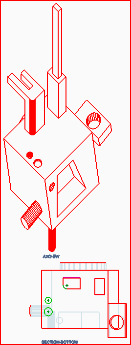 This is 'flat' example.
Feedback please... -
-
@dedmin said:
Please retry... BUT this time move the component/group in question so that it is well out of the same space as the CADup versions... i.e. NOT near the origin... I suspect that there's 'interference' between the original and the copy...
I can perhaps make this a v8 only app and hide the rest of the model...
The idea is you have an instance off to one side and then it makes the 2d parts...
Because it uses raytests and project_to_plane etc it can get confused...
This is still in beta - thanks for the report...

Hello! It looks like you're interested in this conversation, but you don't have an account yet.
Getting fed up of having to scroll through the same posts each visit? When you register for an account, you'll always come back to exactly where you were before, and choose to be notified of new replies (either via email, or push notification). You'll also be able to save bookmarks and upvote posts to show your appreciation to other community members.
With your input, this post could be even better 💗
Register Login


Advertisement