Re: [Plugin] Flatten to Plane v1.2 20101023
-
Ok, I must be doing something wrong. I am building a model wind turbine and want to cut out blades for the model. The blades wrap around a frame in a helical design. I want to flatten the helical shape so that I can get the 2d curve that best approximates the shape of the blade. So I download both plugins and select a plane and select my model. I run the flatten plugin and I now have a blue box around my model blade, but it is still in 3 dimensions. Any ideas as to what I am doing incorrectly? This looks like a great plugin and is just what I need to get my new business started if I can make it work! Thanks in advance for your help.
-
Gude
I can see the problem...
I can't see see what's causing it [yet]
I think perhaps you need Jim Foltz's 'unfold.rb'.............. -
@powerwall said:
Ok, I must be doing something wrong. I am building a model wind turbine and want to cut out blades for the model. The blades wrap around a frame in a helical design. I want to flatten the helical shape so that I can get the 2d curve that best approximates the shape of the blade. So I download both plugins and select a plane and select my model. I run the flatten plugin and I now have a blue box around my model blade, but it is still in 3 dimensions. Any ideas as to what I am doing incorrectly? This looks like a great plugin and is just what I need to get my new business started if I can make it work! Thanks in advance for your help.
This tool only 'projects' a form onto a plane [when it's working!] - if you want to 'unfold' a form use Jim Foltz's 'unfold.rb'..........
There is is also 'flatten.rb' from Smustard ? -
Here's an alternative 'Silhouette to Plane' Tool http://forums.sketchucation.com/viewtopic.php?p=281445#p281445
-
Thanks so much for the info on the unfold tool. This is exactly what I need to convert the 3d curve to a 2d shape that I can have manufactured. I have my first customer for my wind turbine design but the blade design has been a hangup as my manufacturer was unable to determine the curves to cut for the blades. Not knowing CAD, I was at a loss. I can't put into words how great it is to have a solution. Thanks a million!
Keith Tully
Power Wall Systems
http://www.powerwallsystems.net -
SU 8 versionHello,
first I must thank you for your marvelous plugins.
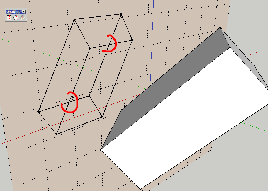
so I try this one and exept for the workplane coplanar to the ground the result is not coplanar with is workplane but seems to be perpendicular.
SU 8 on mac 10.6
see attatchment.
-
I think the problem lies with the transformations of the WorkPlanes...
If you simply move / rotate the WorkPlane group then the tool will use its 'plane' correctly - as the WorkPlane is effectively 2D and its bounds are not orthogonal to the main axes.
You seem to have unlocked and edited the internal contents of the WorkPlane group so that they are then angled within the group and therefore whilst the group is 'orthogonal' to the axes the plane's face is not: because the tool takes the WorkPlanes group's transformation to place the 'flattened' version it appears 'orthogonal' matching the WorkPlane group's alignment and not the internal 'face'...I can probably trap for this too...

-
Here's v1.2 http://forums.sketchucation.com/viewtopic.php?p=281320#p281320
The correct Plane of a 'WorkPlane' is now used even if it has been Transformed inside its own Group. -
sorry for the stupid question, but I can't test this at the moment.
does this script take geometry and lay it flat, or does it create a projection onto the work plane?
I'm looking for a script that will take a bunch of randomly oriented faces and lay them out nice and flat on the ground plane. For lasercutting, so I don't want them projected/distorted.
Thanks,
C -
@manamana said:
sorry for the stupid question, but I can't test this at the moment.
does this script take geometry and lay it flat, or does it create a projection onto the work plane?
I'm looking for a script that will take a bunch of randomly oriented faces and lay them out nice and flat on the ground plane. For laser-cutting, so I don't want them projected/distorted.
Thanks,
CThis tool makes a 'projection' of the vertices in a shape to the nearest points on a plane.
Therefore if the object is skewed relative to the plane its projection will be distorted compared to its 'parent'.
This tool and its sibling 'SilhouetteToPlane' are very similar - this one projects vertices into new lines and keeps grouping etc whilst the other makes a cardboard-cutout silhouette of the 'profile' and faces it.
To lay the faces in objects flat onto the ground I suggest you try Jim Foltz's 'unfold.rb' - it's not 'automatic' but it's easy enough to use...
Are your faces individually grouped?
If so it might be easy enough to script a tool to transform them all 'flat' [normal=[0,0,1]] and all moved to be on the ground - z=0 - you might need to do some tidying if they overlapped etc... but another algorithm to shift them around once they were 'flat' so their bounds didn't intersect would also be feasible...
Adding text-tags to the grouped faces and their 'flattened' counterparts would also be helpful to keep track of them?

-
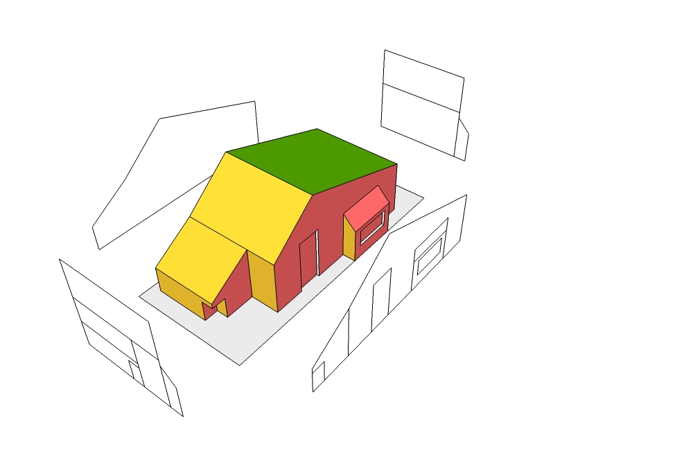
Could someone provide a few worked examples where this tool, and Silouette to plane, prove useful? I am still not clear on function.
Thanks!
Bob -
See this...
-
Dear TIG,
Many thanks for the illustration. So, am I right in thinking that this tool could be used to create third angle projects? Presumably, after using the flattening to plane/keep all edges tool, one could then delete unwanted lines and/or change lines to construction lines to show hidden detail?
Kind regards,
Bob -
@watkins said:
Dear TIG,
Many thanks for the illustration. So, am I right in thinking that this tool could be used to create third angle projects? Presumably, after using the flattening to plane/keep all edges tool, one could then delete unwanted lines and/or change lines to construction lines to show hidden detail?
Kind regards,
BobThat's the idea

-
works great now.


thanks a lot -
Dear TIG.
I'm using this script to project elevations from a model. Its working flawless. Now I wanted to project a 2d of the model that is just visible from a plane And this requires me to select faces with visibility criteria from a given view.
I am doing this with a the following method but I hope there will be a better of doing it.
** Give a colour to my elevations for different views. For example faces that qualify to project on front be coloured red, side views colored yellow etc. then select by similar material and project selection to the working plane.
Faces that are visible on more than one elevation will be given another color and included in selection. **As faces that are perpendicular to my working plane do not need to project these may be selected and hidden on projection just to refine the criteria.
Is there any criteria that evaluates faces in the model according to their visibility from the working plane?
Assuming that our model is opaque and rays from my working plane get reflected to the projection plane.
I.e for Not projecting rear side view on the front one etc ...
Thanks lot again.

-
It projects all selected faces - so to not include the rear don't select it ?
-
got some strange trouble


-
Dem
What's the problem ?
Are you saying that the new 'flat' lines cross each other and they don't 'break' ?
If so, then that is how it should be - the 3D edges are projected flat onto the plane.
If you want the new lines to intersect, then select all of the geometry inside its group and 'Intersect with Context', so that they all split themselves where they cross... It's a quick fix if you are looking to erase some bits later...
Like this -
oh thanks!!!

Advertisement


