[Plugin][$] Curviloft 2.0a - 31 Mar 24 (Loft & Skinning)


-
I use Curviloft a lot, I LOVE it. Can't be without it.

But it does have some limitations and quirks.

One of the quirks I have learned to work around is CL's occasional failure to form some curves even when the perimeter seems fully intact and pristine. I can only attribute its fail to loft due to the connecting geometry in my model. Most likely due to very tiny undetectable fragments and/or gaps. Most times it works, but sometimes I need to do this.....
I select all the lines in my perimeter that failed to loft, and move/copy them some distance away in an axis direction, in free space. Fixing it in free space is far easier than in-situ.
CL will then loft in most cases.
 I simply move the group back in place.
However, sometimes it will still fail, so I look for changes in colors at endpoints. That usually signals a problem at the vertex and/or with the adjoining lines. I do a left/right select on only one side of the vertex and capture everything that touches the vertex, and delete. It also captures one line as well, leaving a gap. I do an endpoint to endpoint line draw and try CL again. Repeat until success.
However when you move the lofted group back into place, and explode it, you will need to redraw many connecting lines in the adjoining geometry, as those lines will have endpointed on the deleted entities. Your primary clue is failed faces touching the lofted curve.
 Please note that the biggest cause of tiny line fragments and tiny gaps is Intersect. So if you are lofting any part of a previously intersected geometry, expect problems. Another big cause of tiny endpoint gaps is drawing a line from point A to B where B is ever so slightly off axis to A and the dreaded "Constrained by" message was not heeded. You need to make sure you draw endpoint to endpoint.
If you do get the "Constrained by" message going from A to B, then Escape, and draw B to A. It will work then. -
@jgb said:
But it does have some limitations and quirks.
After your explanations I'm not sure if it is really the plugin

-
To all,
I need to revisit Curviloft to better control situations where the geometry has a problem (remember that it is still a beta).
In some cases, Curviloft may not perform the generation of shape, but usually there is an error message in the console.
I'll check however if this is always the case.
Fredo
-
@daloop said:
Attached is a lofted version I did last week. It is much more along the lines I need, as it is less concave than yours. It could be, though, that I broke the curve by lofting another, adjacent surface. But not into more than 2 pieces.
[attachment=0:2ad9ldbh]<!-- ia0 -->Loft13.zip<!-- ia0 -->[/attachment:2ad9ldbh]
Any idea how to control the concavity? I can't change the Bezier curves, as they have real-world constraints.
I did try Soap Skin & Bubble but I like the Curviloft surface better.I am not clear how you could have used Loft along Path for generating this shape (I see no path and no base shape).
With Skinning, Curviloft consider that sharp angles in the contour are taken as breaker until it can cut the contour in 3 or 4 pieces.
Anyway, as I told you, the best plugin for this kind of potatoid shape is certainly TGI3D. It uses another algorithm which is more adapted when the contour is continuously smooth.
Fredo
-
@fredo6 said:
Anyway, as I told you, the best plugin for this kind of potatoid shape is certainly TGI3D. It uses another algorithm which is more adapted when the contour is continuously smooth.
Thanks for the tip, but I tried TGI3D. The Training Edition won't mesh my curves and there is no money for software in the budget for this project.
Anyway, thanks for your great plugins and your support. I hope you will continue to develop them. An updated version of your Bezier tools would be nice. They are very powerful but can be a bit finnicky, handling-wise.
-
@cotty said:
@jgb said:
But it does have some limitations and quirks.
After your explanations I'm not sure if it is really the plugin
I can show you many examples of its limitations and quirks. I'm sure you could too, if you use it a lot.
The problem I wrote of is not really an example, in that the perimeter geometry is a user problem, not a CL problem. But how CL handles some perimeter problems does exemplify its "limitations and quirks".
In that case, why would CL not skin a selected perimeter in-situ with other geometry, yet skin that EXACT same perimeter selection when copied away from any other geometry? Doesn't happen all the time, but not often enough to sense an underlying pattern.
-
...after a few hours trying to make it come up in Sketchup13, yes very happy!

-
NEW RELEASE: Curviloft v1.3a - 27 Nov 13
Curviloft 1.3a is a release for future Sketchup compatibility. It is advised to upgrade even if there are no functional changes.
See main post of this thread for Download.
Fredo
-
Hey Fredo Wow Great Plug in but I am trying to make a ship Hull...kinda like your profile picture shows. since most people use the loft to the most in building ships or planes or cars to name a few can you show a tutorial or maybe even explain how one would make a ship hull for say like a pirate ship...anyway good tutorials still tryng to figure out the plugin
-
@thedevil said:
can you show a tutorial or maybe even explain how one would make a ship hull for say like a pirate ship...
It really all boils down to what you have to define the curves needed to generate a loft.
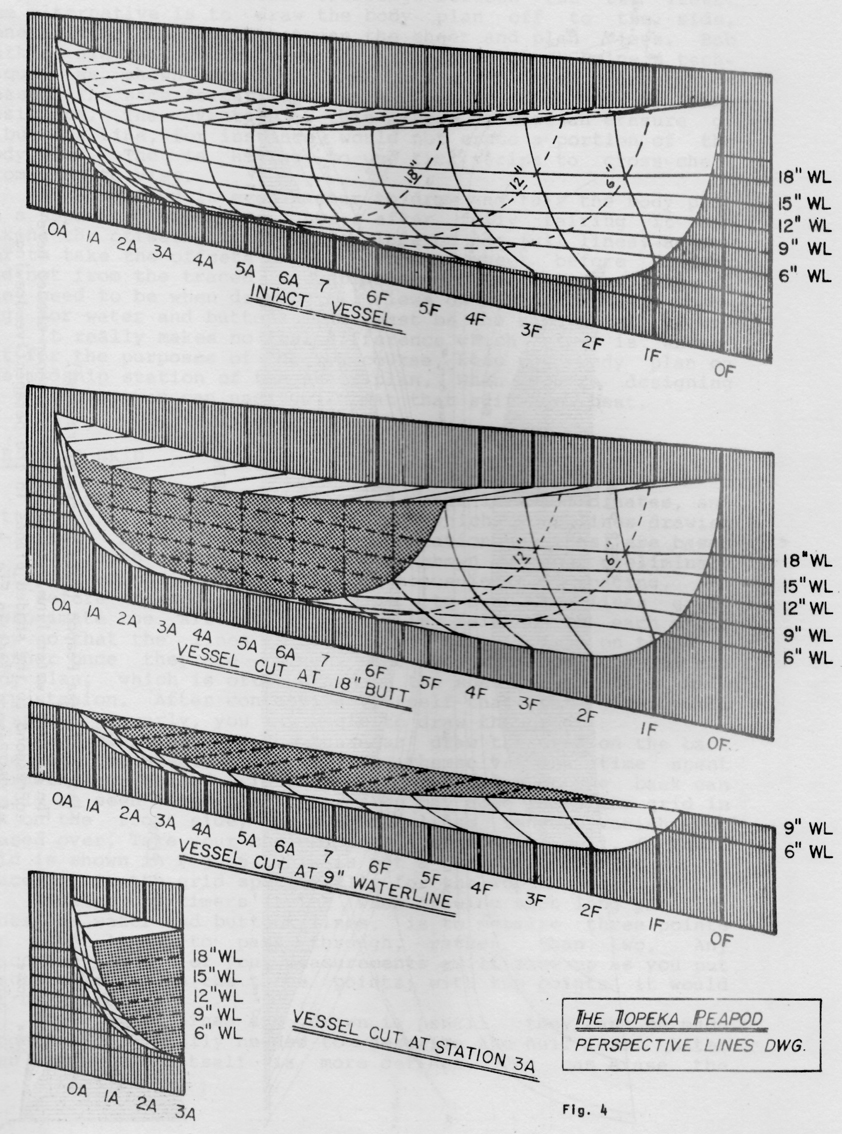
For a ship, you need to define the deck curve (waterlines), the keel curve (buttock lines) and at least 1 (preferably 2 or 3) curves defining the shape of the hull (station lines).
Do a 1/2 hull only. When done, make the loft a component, then copy and flip it for the other side. That way edits to one side are reflected to the other side.
Best practice is to make the 1/2 hull in 3 pieces. The bow section, the hull section, which is usually a straight extrusion for a "pirate ship" type hull, and then the stern section. Merge the 3 sections into one 1/2 hull.
When you create the perimeter curves, pay extra attention to the endpoints where the 3 curves meet. They MUST be attached at the same endpoint. A "constrained" point will NOT loft.
Try to maintain a very similar length of all the defining curve segments, or you will end up with a myriad of tiny triangles.
If you need more help, post here again.
-
Here's a good illustration showing the lines used to define a boat's hull. The sheer line at the top (JGB's deck curve), waterlines (horizontal lines parallel with the water, not curved), stations (vertical sections that run laterally across the boat's centerline) and buttocks (the sections shown perpendicular to the waterlines and parallel to the longitudinal centerline). You can construct these from a table of offsets if you can find it for the vessel you're drawing. You might also get the diagonals which will give you a double check for the other lines.
-
I wasn't sure how much nautical knowledge he had so I tried to keep it very simple.
And that IS a good illustration, BTW. -
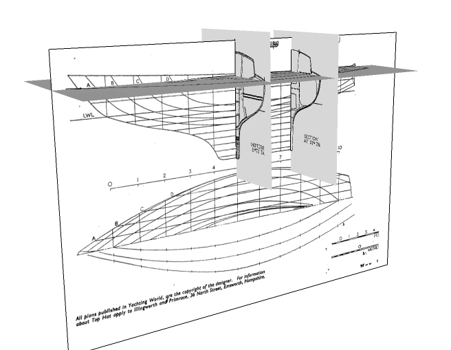
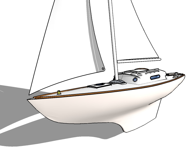
And here's the same idea again but in SU ready to have the lines traced.
(Plans scanned and imported as images).And below is the (un)finished result. Not sure I will ever finish it.
-
guys, how could i make a surface from those contours? just a narrow face beetween the lines

thnks
-
There could be a number of things preventing the completion of the face within the lines. If you post your .skp file, others can review and advise.
It could be a scale issue.
It could be a non coplanar issue.
It could be a non closed figure.
It could be something else. -
CL will fail on any one of the following most common conditions... (as well as a few others)
- 2 lines not joined at "endpoints" although they look like they do. Endpoints joined when "Constrained by" will not loft.
- a tiny fragment at an endpoint is taken as part of the perimeter CL finds, or you define by selection.
When CL defines its perimeter, use the colours as a guide to where problems may lurk. Fredo has stated that the colours are not meaningful by design, but I have noticed that if the perimeter segment is a complete yellow it has no problems, but that is NOT a given. It can be almost any other colour, and it could still have a problem, usually at the very ends. However I have found that red indicates a problem that could be at either endpoint, or anywhere on the curve.
If a perimeter is made up from several colours, then there may be a problem at the endpoints where the colour changes.
The common fix is to zoom in on the endpoint CL has indicated to perhaps be a problem, and fix it.
Another way is to widely left-to-right select one line segment that includes the 2 endpoints and delete it. That will get rid of any gaps or fragments. Then redraw endpoint to endpoint. Make sure you do not join the lines on an endpoint that is "constrained by" or that is on a point outside the current context.
On a large complex loft you may want to put temporary lines in to breakup the large curve into several smaller ones, and CL each of them. The one that will not loft contains the problem. All this does is narrow down where to look. Delete all the temp lofts when done.
On a long complex curve as you posted, I would split it in a binary fashion. CL one 1/2. If it lofts, split the other half in 2 and repeat. If it fails, split that in 1/2 and repeat. Do this until you get down to a manageable few lines to look at in detail. This does not preclude multiple problems, but it does find clean sections as well as the problem ones.
And finally, when CL does not loft a seemingly clean perimeter that is attached to other geometry in the model, do this;
Select all of the perimeter lines manually and move/copy them to some free space along an axis line. You could also make the perimeter a group and edit the group.
Inspect and fix the perimeter for gaps and fragments.
CL should then loft.
Simply move the grouped loft along the axis back to its original position. -
@jgb said:
CL will fail on any one of the following most common conditions... (as well as a few others)
- 2 lines not joined at "endpoints" although they look like they do. Endpoints joined when "Constrained by" will not loft.
- a tiny fragment at an endpoint is taken as part of the perimeter CL finds, or you define by selection.
you keep saying this stuff but it's not curviloft which is failing..
unless you also consider sketchup itself is failing at creating a surface to my square in this scenario: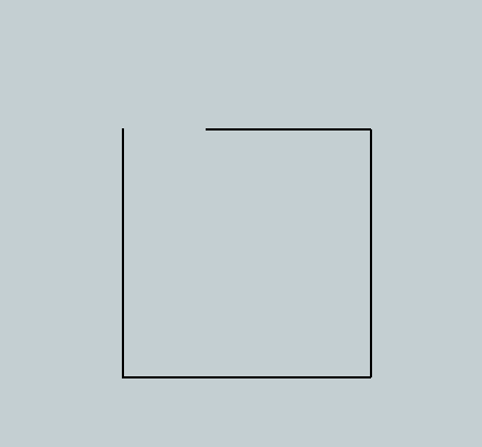
and your situation '2' is just poor user selection.. i'm not really sure what you're expecting the plugin to do in that scenario..
-
@yanosiento said:
guys, how could i make a surface from those contours? just a narrow face beetween the lines
http://s14.postimg.org/oebxw5ab5/d_vida.png
thnks
from the image you posted, it looks like all you would have to do is select all of it then use curviloft's skin contours function. (the 3rd icon in the toolbar)
-
If none of the preceding comments apply or fix your issue... then please attach a SKP to a post and we'll look at it...
It will be 'do-able'...
-
Jeff
You are being picky.

Of course the "fail to loft" is not a CL fault. It is the geometry faults that "prevent" CL from lofting.
Hello! It looks like you're interested in this conversation, but you don't have an account yet.
Getting fed up of having to scroll through the same posts each visit? When you register for an account, you'll always come back to exactly where you were before, and choose to be notified of new replies (either via email, or push notification). You'll also be able to save bookmarks and upvote posts to show your appreciation to other community members.
With your input, this post could be even better 💗
Register Login


Advertisement