[Plugin][$] Curviloft 2.0a - 31 Mar 24 (Loft & Skinning)
-
The upper variant (on the attached picture) made with Soften dialog. My humble request is to get this result automatically (like profile builder does) without manual polishing afterwards.
-
Turn "Show Hidden Geometry" on. Then using the "shift+Ctrl+erase tool" select the lines you want unsmoothed and unsoftened. You can play with combinations to get smooth unsoft or soft unsmoothed lines and that will take care of your over smoothed surfaces.
Then turn show hidden geometry off.
You can also select any line(s) and change the smooth or soft or hidden attribute in Entity Info.
-
Again, I suggested kind of more intelligent smoothing (similar to follow me or profile builder) IN plugin itself
Edit: extra pic added to illustrate the problem
-
The top back edge is also smoothed. If you unsmooth just that line and the one below (in the back) then the top will not be over smoothed.
The only other way you can get less smoothed top surface is to create a small smoothed radius on the top & bottom back edges. The size of the radius will control how much smoothing you do want.
-
Have used your plugins for years. Now I can't load them.
Installation of Fredo6_Curiloft; Freddo6_FredoTools; Freddo6_Joint PushPull;
Subfolder missing.
Tried to install roundcorners from extension manager but it failed.Tried to install LibFredo6 11.8a. received error message:
“undefined method ‘loadRBS’ for SCF:ModuleAny advice on what I should do.
-
You might try updating the Sketchucation Extension Store installation. https://sketchucation.com/pluginstore?pln=SketchUcationTools
-
Tried that, then tried to load Roundcorners and got this result:
UnZip Error: Could not unzip archive.What next???
-
When you say you tried 'to load' RoundCorners, how did you do that ?
There are two main ways...
-
download its RBZ file and use the SketchUp Extension Manager dialog to Install it...
-
auto-install it using the SketchUcation ExtensionStore³ dialog - find its entry and click to install.
Also remember that Fredo's tools need his LibFredo installing...
Also remember to restart SketchUp after the installations to ensure everything is synced...
After it's all successfully installed there should be tool-menu entries and toolbars etc...
PS: If you have recently updated your SketchUp installation it must be installed by selecting the downloaded installer's exe file, right-click, context-menu > "Run as administrator", with an existing installation choose 'Repair' when prompted...
Installing Windows apps in any other way, e.g. by double-clicking the exe to 'run' it, can lead to all sorts un unpredictable issues, usually affecting folder permissions etc...
Your normal user-account might have admin-powers but it it is not the same as doing it properly.It does no harm to do the 'Repair'...
-
-
Thanks for your help, however i have tried all that.
When I start Sketchup the first notice on screen is
"Installation of Fredo6_Curviloft is probably incorrect. Subfolder is missing."I press OK and then get the same message for FredoTools; JointPushPull and
"Script ToolsOnSurface is loaded but menus will show up only at next startup of Sketchup."So I start the program again and exactly the same messages occur.
Tried the autp-install again and got the same message again = "UnZip Error: Could not unzip archive."
I'm running 2020 version of Sketchup.
Cheers
Graham -
The
UnZIPerror message suggests that the destination folder is not fully writable and SketchUp cannot unzip the RBZ archive into it ?
This can be a typical permissions error when an installation was not done using "Run as administrator"You have not stated categorically that you have done the installation properly, or repaired it later...
Assuming you have repaired things but it's still not working then can you close SketchUp, and then find your
Pluginsfolder which is in the folder
C:\Users\YOURUSERNAME\AppData\Roaming\SketchUp\SketchUp 2020\SketchUp\
It's hidden by default, but using its path in Windows Explorer should get you there...
Select thePluginsfolder icon, right-click > context-menu > Properties > Security
There will be several Group/user names listed - e.g. SYSTEM, maybe-Unknown [SketchUp?], Your user-name and Administrators etc...
Use the Edit... button on each entry in turn.
The entry's Permissions must be ticked to 'Full Control' > under the Allow column
After fixing all of these OK to save the changes, the changes should ripple down to affect any subfolders/files etc...
Restart SketchUp and try reinstalling LibFredo RBZ and any desired RBZ extensions.
Restart SketchUp to sync everything...Report back...
-
Thanks very much for helping me out Tig,
Unfortunately I followed all your instruction, turned everything off and restarted, Still have the same issue.
Sorry.
Graham -
I had the same Script "XXXX* is loaded but menus will show up only at next startup of Sketchup" nightmare (with all Fredo's plugins I have. Its not related to Admin rights (at least in my case). IIRC installing the latest FredoGhost helped.
-
In rare cases there have been reports like this that relate back to a corrupt windows-user-account...
To check this you could try making anew user-account on your computer.
Then install SketchUp for that [run-as-administrator etc].
Then install LibFredo and one of his extensions for that version of SketchUp.Restart SketchUp and see if the issue is resolved...
If so we then need to look at ways of fixing your original windows-user-account, if possible...
If it's not working then the mystery deepens...PS: You could also consider running a file-system check on Windows to see if it fixes anything...
https://support.microsoft.com/en-us/windows/using-system-file-checker-in-windows-10-365e0031-36b1-6031-f804-8fd86e0ef4ca
https://support.microsoft.com/en-us/topic/use-the-system-file-checker-tool-to-repair-missing-or-corrupted-system-files-79aa86cb-ca52-166a-92a3-966e85d4094e
etc... -
-
"Loft by spline doesn't work."
It actually does work with the correct set up. This was done in SketchUp 2021.
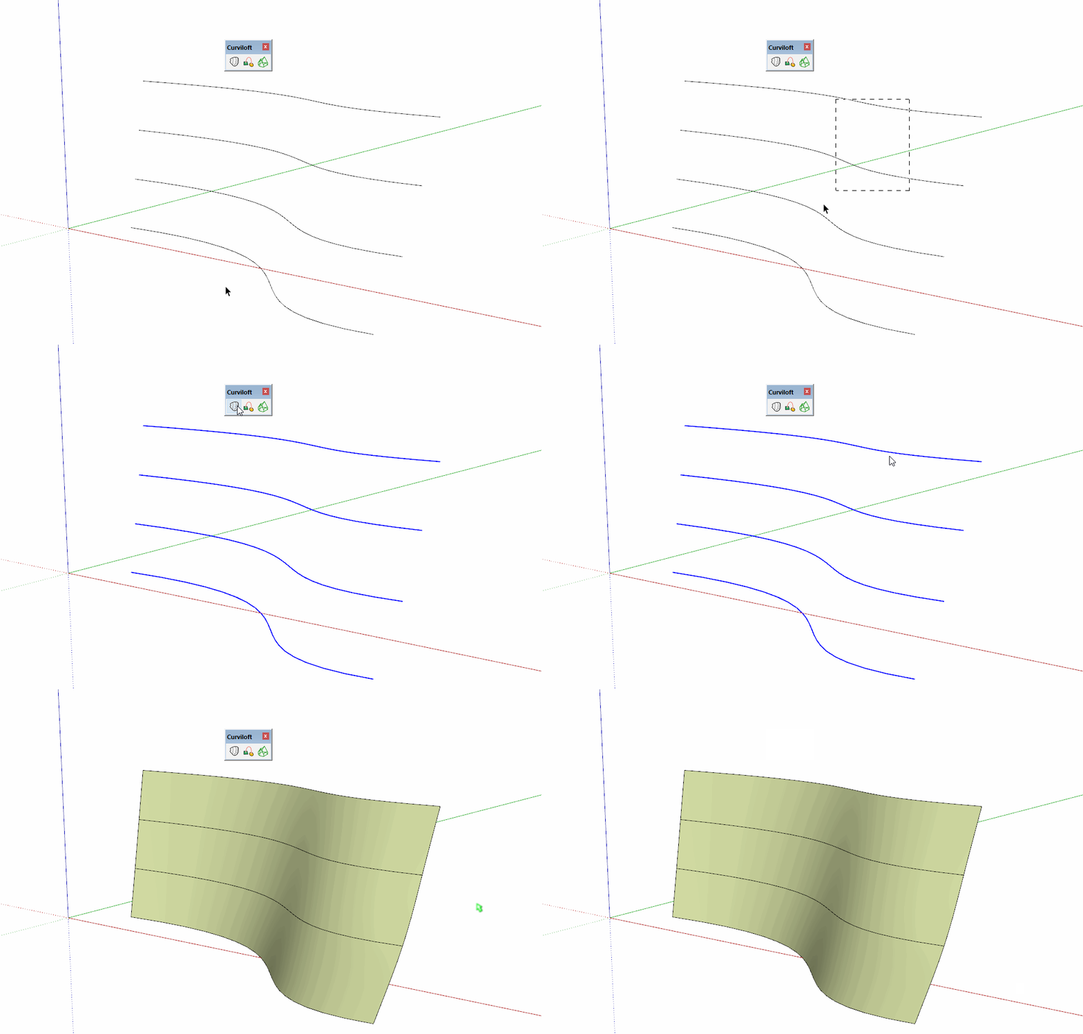
Share the .skp file so we can see what you are working with.
-
Hi,
I've been bashing away at this for hours now, and simply can't find a solution anywhere or work this out for myself. I'm so frustrated with this I've even considered switching to Blender, but wouldn't know where to start with a shape as wonky as this.
The smaller (older) set of curves skin fine in Curviloft, but the others report an error. This is one of the side faces of a jewellery bail, something I've modelled using Curviloft many times over without issue. It strikes me that the curves that skin aren't as clean and smoothly defined as the new ones, but other than that I have no clue.
Any ideas?
Thanks in advance,
Thomas
-
Since the arc at the left end is flat, you could put in an edge to fill that face.
Then run Curviloft for the rest of it.
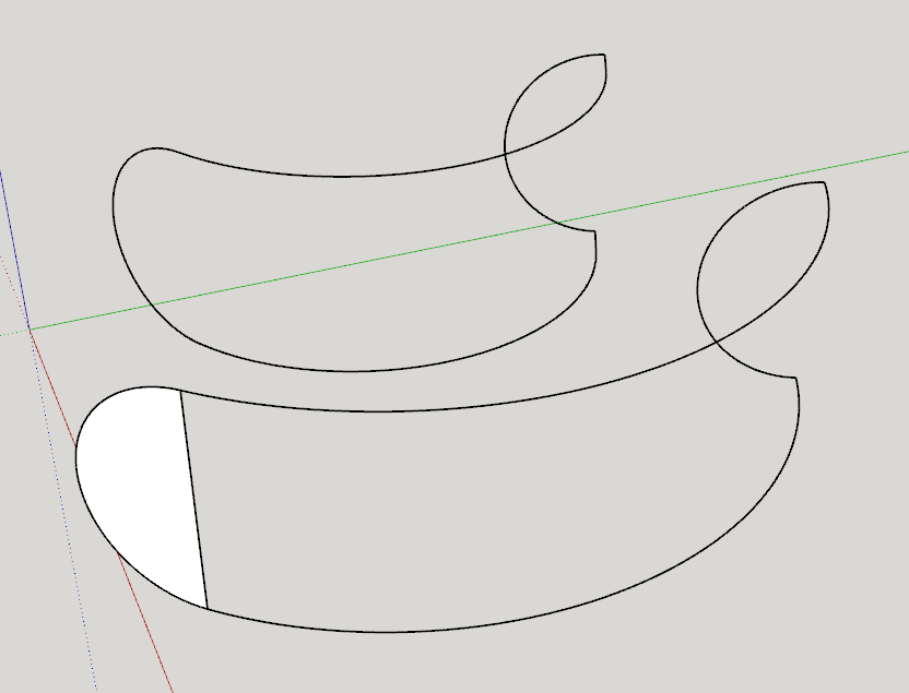
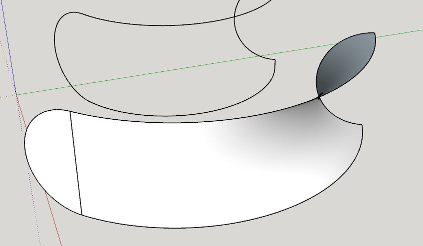
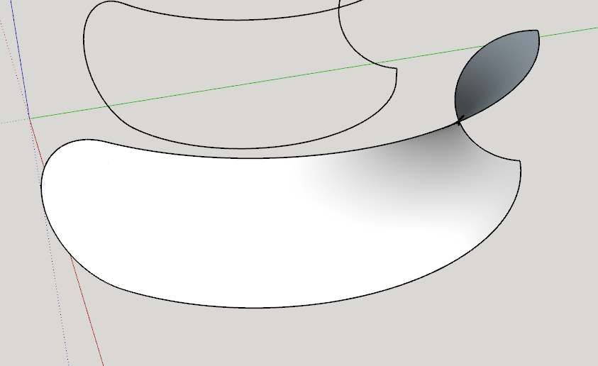
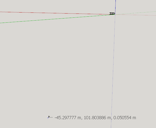
Your smaller one has some stray edges sticking out and there are some strays off at a long distance from the rest of the model. One of them is over 100 meters from the origin. Might want to delete those things.
-
@dave r said:
Since the arc at the left end is flat, you could put in an edge to fill that face.
Then run Curviloft for the rest of it.Your smaller one has some stray edges sticking out and there are some strays off at a long distance from the rest of the model. One of them is over 100 meters from the origin. Might want to delete those things.
[attachment=0:1af6ujpi]<!-- ia0 -->Screenshot - 2_4_2022 , 1_21_59 PM.png<!-- ia0 -->[/attachment:1af6ujpi]
Dave, that is incredible, thank you!

Yeah, that took like under a minute to fix.
I owe you one, seriously

Thomas
-
@aibonewt said:
Yeah, that took like under a minute to fix.
Happy to know it got you sorted out.
Because I'm nosy, what are you modeling?
-
@dave r said:
@aibonewt said:
Yeah, that took like under a minute to fix.
Happy to know it got you sorted out.
Because I'm nosy, what are you modeling?
Hi Dave,
I'm making resin pendants from 3D printed moulds, and the lofts are part of the bails that contain the cord. I've done hexagonal and circular previously, now I need to create one to fit the square (rotated 45°).
Thanks for you interest,Thomas (T/A @lightandmagik)
Advertisement


