Help Me Draw A Dome [TUTORIAL]
-
Okay, no problem, there is an easy fix.
This is actually what I wanted to avoid by hiding the inner dome (as its hidden edges now intersected with the outer dome as well). No problem however - apart from the intersection lines we wanted to create, now new geometry was created - just old, softened edges hardened.There could have been a whole bunch of ways to avoid this - I though I found an easy one and I don't know why it didn't work for you as I cannot "Undo" your steps once you closed the model.
Anyway,
- go into the group again,
- select all by triple clicking,
- right click and choose "Soften/Smooth edges.
- When the popup opens, make sure that "Soften coplanar" (edges) is NOT checked and move the slider a bit (just enough to "touch" it).
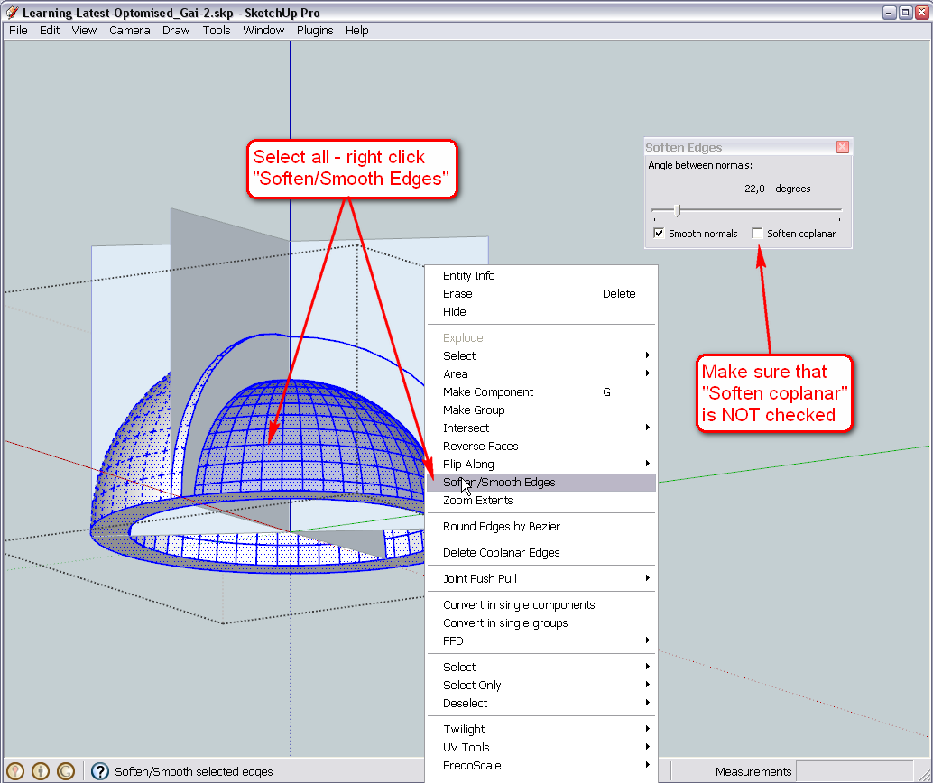
Since we have rotated our slicing planes to the midpoints, we cut the facets in the middle thus creating two but perfectly coplanar ones of each. This is why we can use this trick now and soften everything else BUT what we actually need.
When you have done this, you will be able to go on cleaning the stuff.
If the other dome behaves the same, naughty way, deal with it similarly.
-
Hi Gai
After my last post, I decided to take another stab at it.
I made a backup of the file before proceeding with intersection, so I restored the backup and from the top of you instructions, I went through again step by step and voila!!! I got. Immediately after succeeding, I refreshed the page and then found your post with the solution. It's actually a good thing I saw your post later late. Gave me a chance to overcome the hurdle. I love challenges and that's the best way to learn. I learned something about SU. It is very sensitive to clicks in terms of where you click, how many times you click and so on.It's really overwhelming when the problem is resolved after numerous attempts.
I've attached the latest sketch. As you can see, I've left the slicing planes. Wasn't too sure whether to delete or hide them.
I must thank you for your patience. I am a bit of a slow learner but grasping on quite well.
So where to next, teacher?
Regards
D0me
-
Okay - downloading...
-
Hi
Thought I'd let you know that I used the instructions from your last post to resolve the promlematic file named Learning-Latest-Optomised_Gai-2.skp and I was successfull there as well.
Thanks
-
@d0me said:
I've attached the latest sketch. As you can see, I've left the slicing planes. Wasn't too sure whether to delete or hide them.
Well, we won't need them any more so you can safely delete them. Also, open your Layer dialog (Window menu) and delete the slice layer (I left it there) and delete its content, too (there are my slices)

@d0me said:
Thought I'd let you know that I used the instructions from your last post to resolve the promlematic file named Learning-Latest-Optomised_Gai-2.skp and I was successfull there as well.
Okay, good to know you got that, too.
Also, above my things were not visible (slicing planes and all) because I used that "Hide rest of model" function you also have now with Ctrl+H.
Now, first of all, we need components of these groups (We could also have started with them of course). Components are actually like groups but they have some extra features like you can set their internal axes (see below), can be exported and reloaded like separate skp files, can "glue" to faces (group too but you cannot control that), can cut holes like for openings etc. but most importantly for us now: there is one definition of a component and there can be several instances. SU only "keeps in mind" one definition so if you place a whole bunch of them, it needs to count the geometry only once and remember the place, orientation etc. the instances only. This saves file size and also, if you edit one component and make changes, all the others will reflect/inherit these changes.
Now right click on each group and make component. Immediately after, open your Component browser (Window menu) and go to "In model" and rename your stupidly named components to something meaningful first. Also notice (to your utmost horror) that the component thumbnails are upside down.
The simple reason - remember when your whole model was upside down? Groups also have axes (although we cannot control them) and this state got frozen when you made them upside down. We need to change this (and as we would change the component axes anyway for our task now, as I am sure we will flip/mirror some in the future and that happens along component axes, this is not a big problem).
So right click on one (I chose the inner first) and "Change axes" - hope the image instructions are enough.
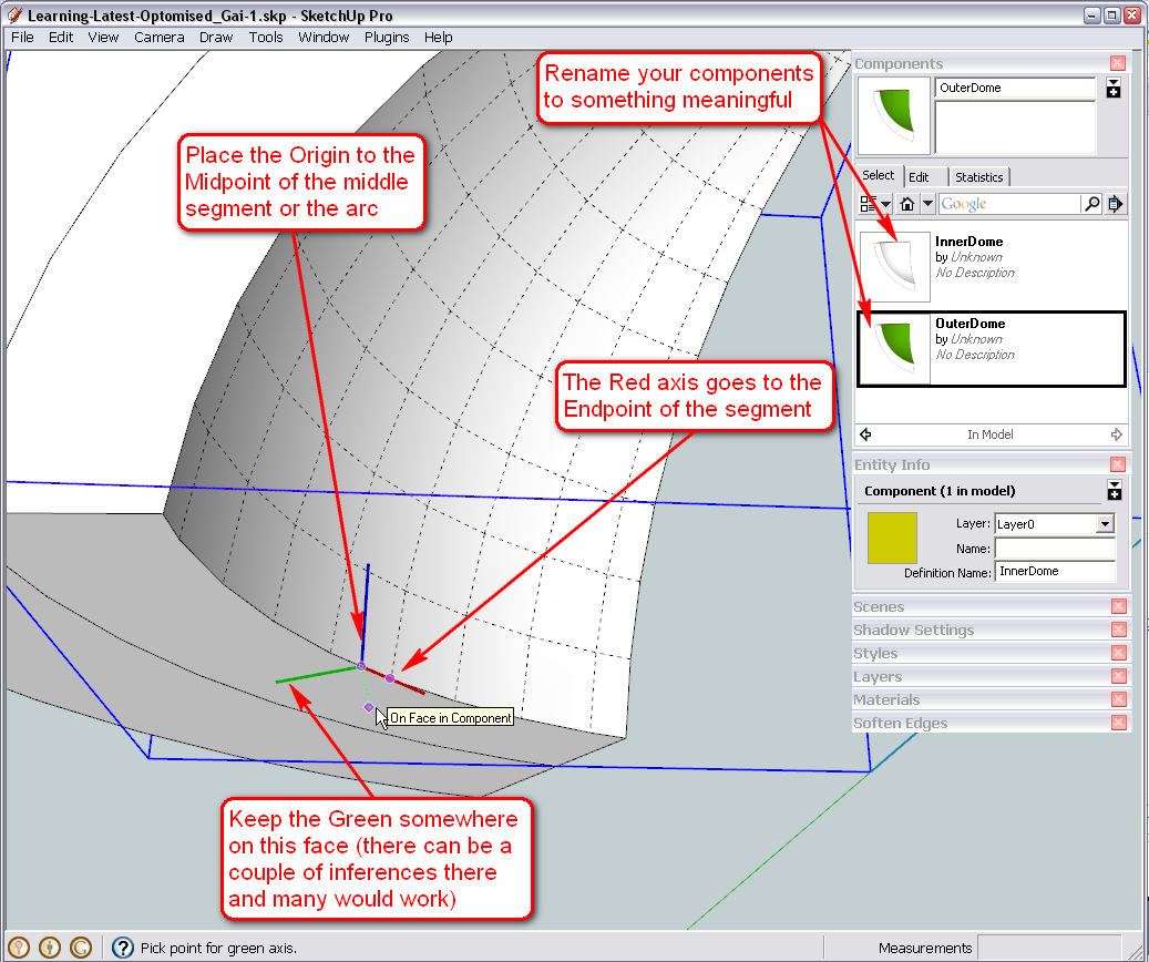
Also, with the outer dome, change the axes similarly (it's now outside but that's not a problem)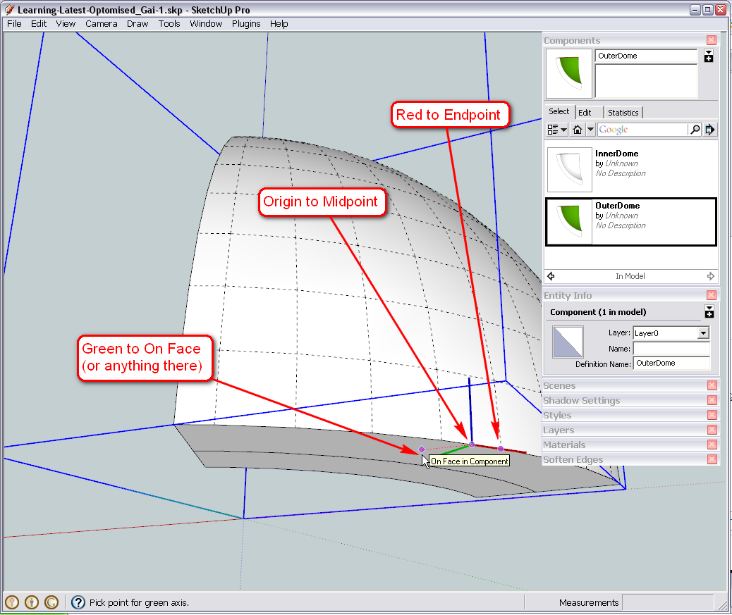
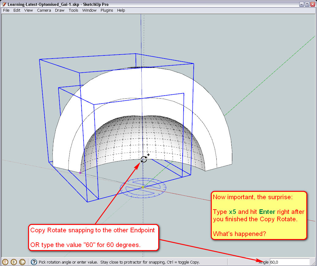
And now we are going to make a "Radial array". Select both components and start like the Copy Rotate some pages above: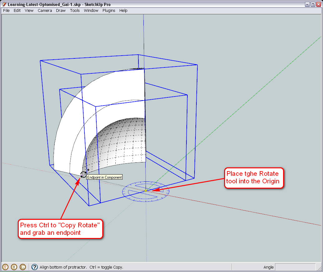
Rotating one instance of the component - but read the yellow label before finishing. What have you got?
-
Cool. Super Cool.
X5 and voila. 5 pieces instantly join to form the dome in its entirety.
Wow, what an accomplishment even though you walked me all the way.
Thanks a millionCan't wait to continue.
-
I just noticed that under Window > Components, the dome is still upside down.
Is that normal?
-
Hi Gai
Sorry for posting in parts, but I was using the orbit tool to look around the dome and then when I brought my dome back to what it was, the entire colouring of the dome went crazy. The dome was in an xrayed format yet I didn't select xray.
Sketch Attached.
-
@d0me said:
I just noticed that under Window > Components, the dome is still upside down.
Is that normal?
Yes, unfortunately the thumbnails do not refresh. I would not call it a bug as they have never "tried" to fix it - rather a lack of feature.
If you want to change that, here is how (and it's a useful tool anyway).
- Right click on a component either in the model space or in the component browser and "Save as..."
- Remember where you save it - and open that file (now also learn that components are actually full fledges skp models - just "embedded" into your model) it will open "normally" - i.e. not upside down.
- Orbit to have the best view as you wish (turn on colours again, turn off hidden geometry) and simply save.
- Now go back to your original model, right click the component again and "Reload".
Now the thumbnail will change, too. Do it - just out of practice, if you wish.
-
@d0me said:
The dome was in an xrayed format yet I didn't select xray.
Well, the dome IS in X-ray. Press the X-ray button in your face style toolbar and it gets back to normal.
Also, maybe it's time to go back to Perspective mode (at least to me, it feels so much more comfortable and natural).Next thing will be that "door" or something. So what are the plans? How big, what shape (maybe arched) etc.?
-
@unknownuser said:
Yes, unfortunately the thumbnails do not refresh. I would not call it a bug as they have never "tried" to fix it - rather a lack of feature.
YOU can fix it - select an instance of the component, and type/paste
Sketchup.active_model.selection[0].definition.refresh_thumbnailinto the Ruby Console to refresh the selected component's thumbnail...
Alternatively, type/pasteSketchup.active_model.definitions.each{|d|d.refresh_thumbnail}into the Ruby Console to refresh all of your component's thumbnails, with no selecting required...

-
An even cleverer way is to write a short script
require 'sketchup.rb'
def refreshthumbnails
  Sketchup.active_model.definitions.each{|d|d.refresh_thumbnail}
end#def
refreshthumbnails
copy/paste this code into a file called
refreshthumbnails.rbin the Plugins folder - that way your component thumbnails will update whenever the model opens and typingrefreshthumbnailsinto the Ruby Console will fix any changed or new components' thumbnails too...

-
Now you've scared poor D0me away I'm afraid, TIG!

But million thanks for this!

-
Just regard TIG's avatar.
Just your friendly local tiger--wagging his tail and licking his lips. -
Hi Gai
Thanks for the solution.
Tig: You almost scared me away but I came back for more.
On a more serious note, time just has not been on my side these past few days and the little free time that I do have gets spent here.Gai: The opening is 18" in width and 9 Inches High. An arched shaped opening sounds good. The opening should be exactly halfway between 2 slices of the dome.
Thanks
Regards
D0me -
@d0me said:
...time just has not been on my side these past few days and the little free time that I do have gets spent here.
No problem, D0me, we have time.

@d0me said:
The opening is 18" in width and 9 Inches High. An arched shaped opening sounds good.
Any thoughts on a wall thickness?

@d0me said:
The opening should be exactly halfway between 2 slices of the dome.
I was like half expecting this. That's why we needed to set those component axes so meticulously as when a component is now mirrored along its red axis, it won't get out of alignment.

Always think ahead - that's the key for SU as though modelling is quite easy, intuitive and the learning curve is not very steep, existing geometry is not very easy to modify.
So let's continue...
In order to easily draw the "entrance" along the regular axes, we will rotate our whole structure a little bit (note that an easier way to temporarily work with different axes could be to place the axes aligned to our structure but eventually it will be more beneficial for us to do it this way).
I have temporarily grouped everything so that it's easier to rotate together. Alignment of the Rotate tool where there is so much geometry around is not easy but you already know two tricks to do it.
Rotate the whole structure in a way that the seam between two sets of components lie exactly on the red (or green) axis.
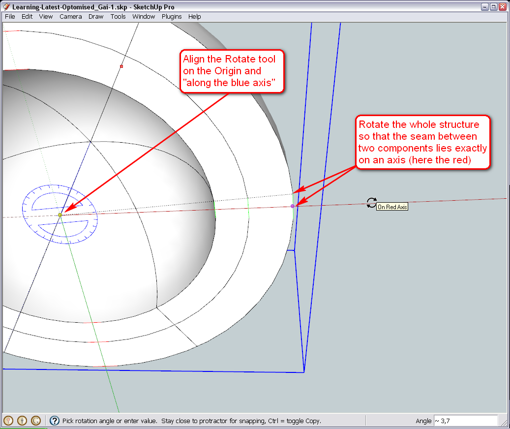
Now as we have learnt, whatever changes we make in one instance of a component, it will chage every other instance, too, so where we choose to make the entrance (as you wrote, "exactly halfway between 2 slices") we need to make unique. Make sure to make those two pieces unique whose seam now lies on the axis you have aligned the whole structure just now.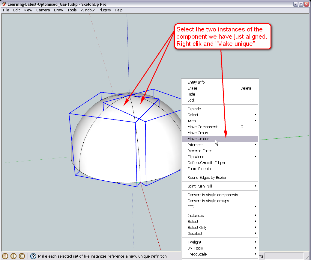
Now I temporarily hid the two new, unique outer dome slices and made the corresponding inner slices unique, too.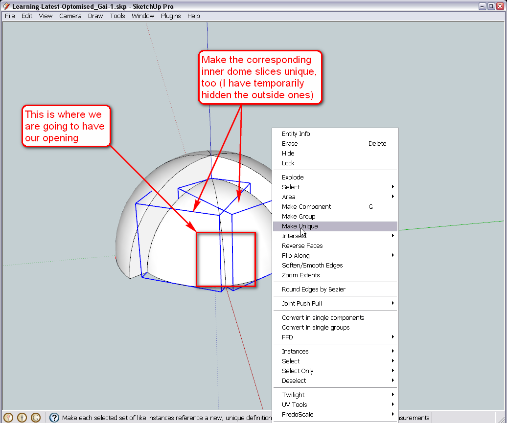
Okay, one more thing. If we start "carving" our entrance into the two slices, one instance needs to be mirrored otherwise both halves of the entrance would appear either on the right or left of each slice. This is when it comes handy that we have already set the component axes properly and we can easily flip the components around their red axes without them getting way out of alignment.
If you turn the visibility of the component axes on (Window > Model info > Components), it is very apparent actually. Here I have already flipped one of the components and you can see that the red axis points in the opposite direction.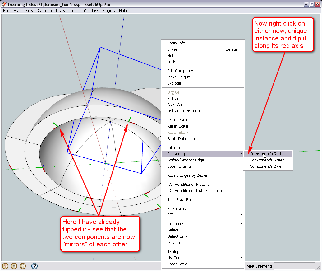
Now unhide the outer pieces and flip either along its red, too (it does not matter which one actually but to keep track what we are doing, best is to pick the corresponding piece - in this case the right one).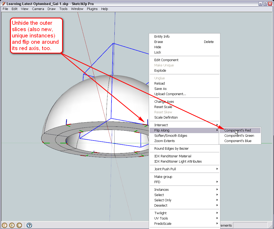
I think we are ready to start designing our entrance now.At this state of the model, I also attach my finished version so that you can compare whatever you end up with, with this one. I think we have lost some colouring somewhere but that does not matter - we can redo that at the end easily again.
-
It's an igloo

-
Yeah - especially with the entrance inserted (I have already tried).

Igloo for dwarves though (mind the scale!)

-
@unknownuser said:
It's an igloo

For 9" high Inuit. I guess they are going to reveal the mystery in the last episode - after all it is a technical thriller.
-
Hi Gai
I'm stuck again.
I did the following.
- I selected my entire sketch, Right Click and selected Make Group
- I then managed to place my rotation tool at the origin along the blue axis and rotated the entire sketch whereby the seam seperating 2 pieces was exactly on the red axis.
- I then selected the 2 pieces sharing the red axis and then right clicked it and selected make unique.
- I then managed to select the top 2 pieces and hide it.
- After hiding the top pieces, I selected the 2 pieces on the inner dome and right click > Make Unique.
- I then turned on the visibility of the component axes.
I am currently stuck at this stage. It seems that my inner dome is not aligned properly for some reason.
I have attached the file.In the interim, I have downloaded the file you attached in your last post. While assisting me in resolving this problem, I'm sure we can go ahead and continue. I can always try to resolve my sketch later.
Look forward to hearing from you
Thanks
Regards
D0me
Advertisement


